Self-Locking Pin
- Summary
- Abstract
- Description
- Claims
- Application Information
AI Technical Summary
Benefits of technology
Problems solved by technology
Method used
Image
Examples
first embodiment
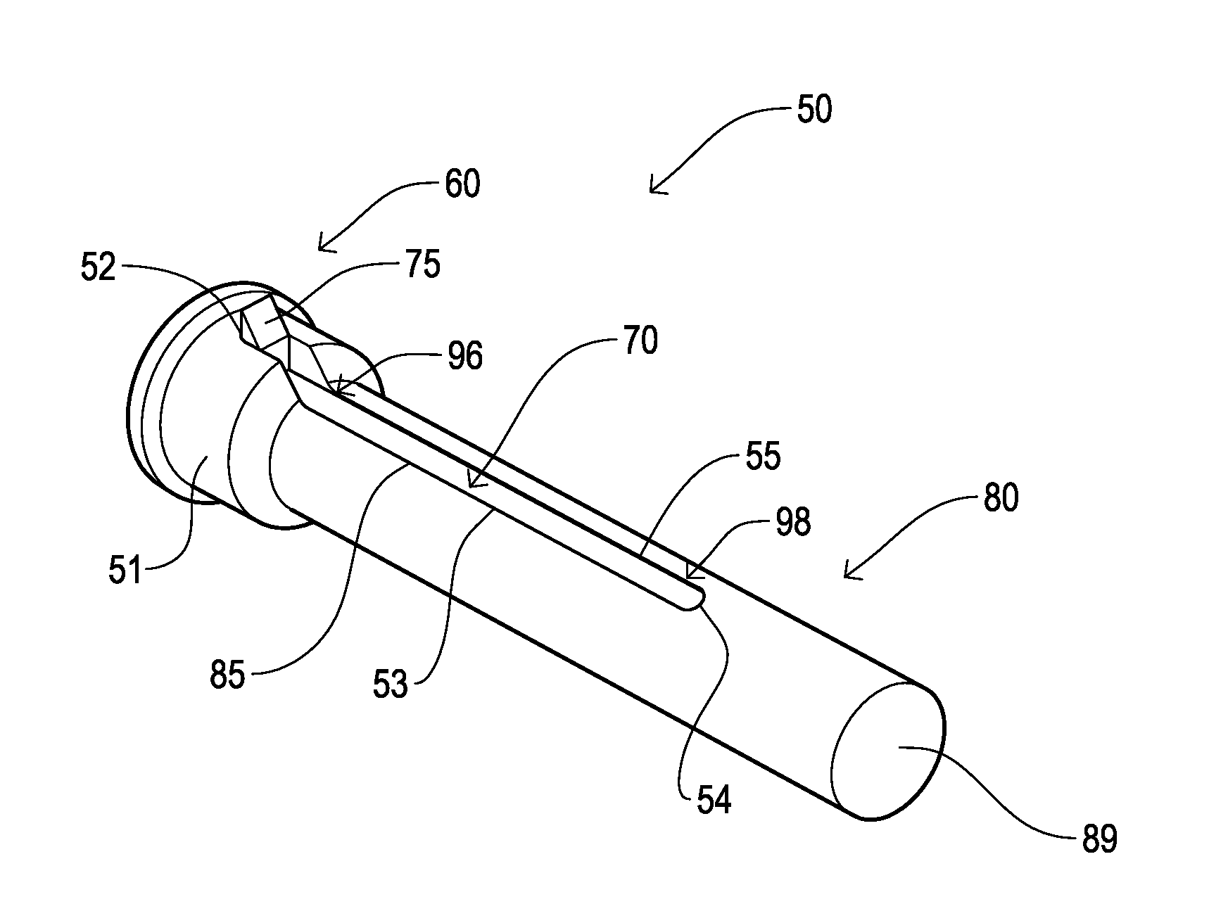
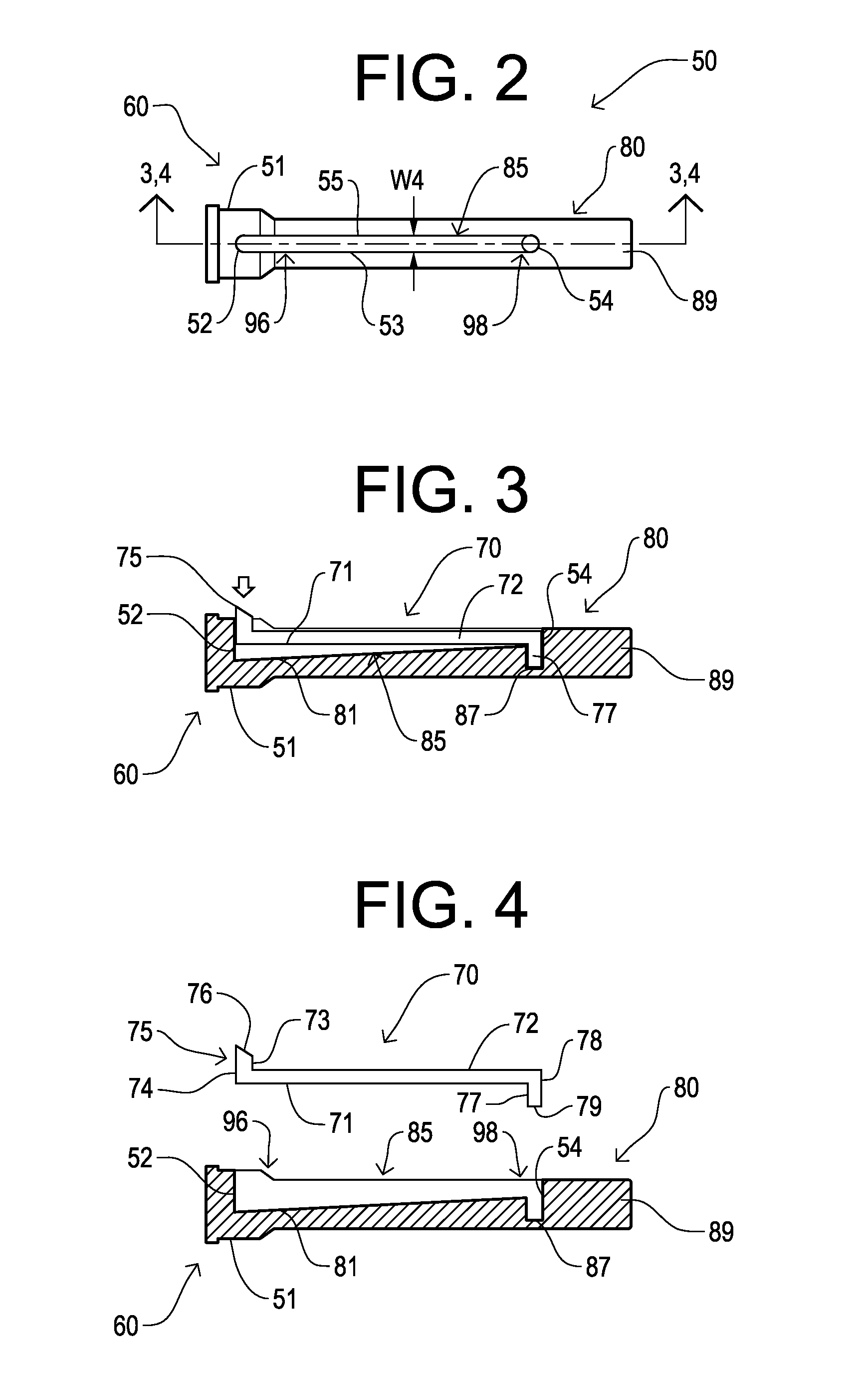
[0043]The shaft 80 is attached co-axially with the head 60. The shaft 80 of the first embodiment is a complex, multi-diameter shaft 80. The proximal wider shaft portion 51 attaches directly to the head 60 and has a diameter that is larger than the distal thinner shaft portion 89. The shaft 80 has an exterior surface 58 that is broken by the slot 85, which extends into both shaft portions, proximal wider shaft portion 51 and distal thinner shaft portion 89.
[0044]The shaft 80 is configured with an open long, narrow slot 85 that extends longitudinally and is configured to receive the detent spring 70. One end of the slot 85 is an anchor end 98 (FIGS. 2, 4) and the opposing end is a latch end 96. The detent spring 70 is anchored in the anchor end 98, and the detent 75 of the detent spring 70 is located within the latch end 96. In the first embodiment, the latch end 96 is disposed at or toward the head end 51 of the shaft 80, and the anchor end 98 is disposed at or toward the insertion e...
fourth embodiment
[0057]The bottom of the detent spring 70 is cut with spring notch edges 91 corresponding to the size and shape of the frustum-to-cone shape projection 97. In cross-section, as seen in FIG. 13, the upper portion of the frustum-to-cone shape projection 97 appears mountain-shaped and the spring notch edges 91 form a corresponding mountain shape to receive the frustum-to-cone shape projection 97 when the pin lock 90 of the fourth embodiment is inserted.
third embodiment
[0058]As in the third embodiment, the insertion of the lock pin 90 secures or locks the spring detent 75 in the outwardly projecting position above the plane of the shaft 80 surface, thus preventing the detent 75 from being accidentally retracted.
[0059]In the second embodiment, the distal end of the self-locking pin 50 was solid from the latch end wall 52 to the outward most wall of distal end 89. In the third, fourth, and fifth embodiments, the distal end 89 of shaft 80 has a cylindrical opening defined by lock pin receiving hole edges 92 or 93, and the latch end wall is a partial wall 88 (FIG. 13). In the fourth embodiment the slot floor area 83 at the proximal end of the lock pin receiving hole edges 93 is preferably flat or generally flat, as seen in FIG. 13.
[0060]In use, the self-locking pin 50 of the fourth embodiment is inserted into the receiving pinhole(s) while the detent 75 is self-retracted. After the detent 75 has passed through the receiving pinhole(s), the detent spri...
PUM
 Abstract
Description
Claims
Application Information
 - R&D
- Intellectual Property
- Life Sciences
- Materials
- Tech Scout
- Unparalleled Data Quality
- Higher Quality Content
- 60% Fewer Hallucinations
Browse by: Latest US Patents, China's latest patents, Technical Efficacy Thesaurus, Application Domain, Technology Topic, Popular Technical Reports.
© 2025 PatSnap. All rights reserved.Legal|Privacy policy|Modern Slavery Act Transparency Statement|Sitemap|About US| Contact US: help@patsnap.com


