
Electronic device

a technology of electronic devices and printed antennas, applied in the field of electronic devices, can solve the problems of difficult radiation to the front surface of electronic devices through display, difficult to achieve electromagnetic waves through rear surfaces, and difficult to achieve the effect of enhancing antenna performan

Active Publication Date: 2019-08-13
LG ELECTRONICS INC
View PDF12 Cites 9 Cited by
  • Summary
  • Abstract
  • Description
  • Claims
  • Application Information

AI Technical Summary

Benefits of technology

[0007]Therefore, an aspect of the detailed description is to enhance performance of an antenna formed of a transparent electrode material within a display.
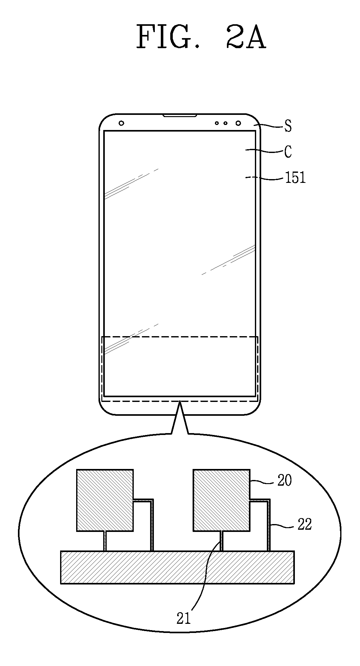
[0010]According to embodiments of the present disclosure, since two sides of the patch antenna perpendicular to each other are slopingly disposed with respect to one side of the display and two feeding lines implementing dual-feeding are linearly disposed to be parallel to each other, feeding loss and radiation loss is reduced.
[0011]Also, since two feeding lines are implemented without being bent, isolation characteristics between ports are improved, enhancing radiation performance. In addition, since horizontal / vertical polarization purity is maintained constant, while reducing loss due to dual-feeding of the array antenna, a variation in performance according to a rotational state of the electronic device, or the like, is prevented.

Problems solved by technology

However, a printed antenna printed on a circuit board developed so far or a chip antenna disposed on a circuit board has a very high loss in a 5G frequency band (for example, 28 GHz or 39 GHz band).
However, when the rear surface of the electronic device is covered with a palm of a hand, it is difficult for electromagnetic waves to be radiated through the rear surface.
Also, radiation to the front surface of the electronic device is difficult to pass through a display.

Method used


Image

  • Electronic device
  • Electronic device
  • Electronic device

Examples


Embodiment Construction

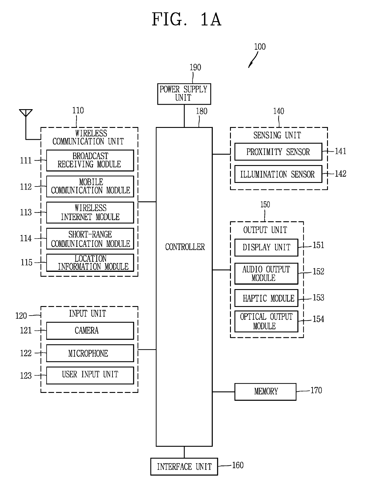
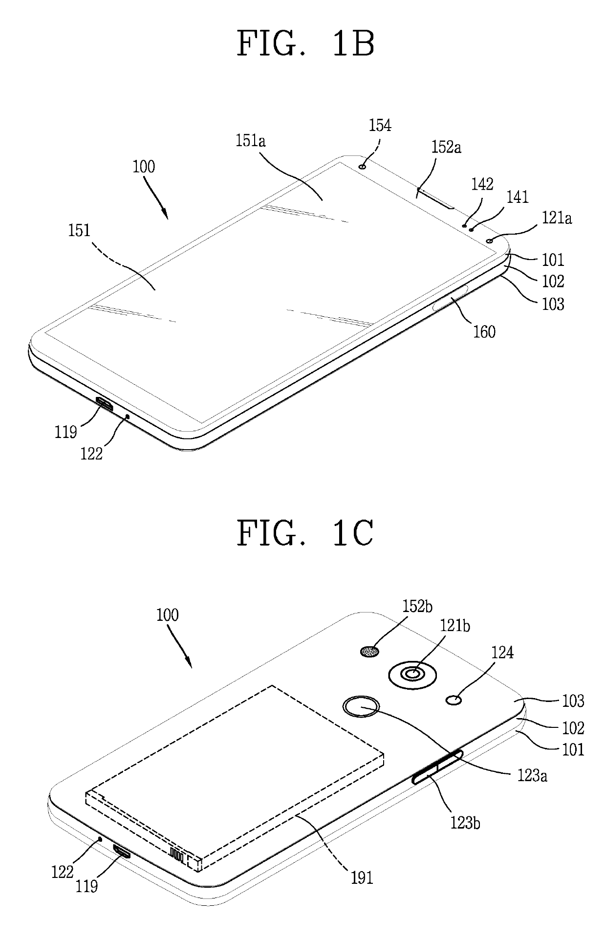
[0029]Description will now be given in detail according to exemplary embodiments disclosed herein, with reference to the accompanying drawings. For the sake of brief description with reference to the drawings, the same or equivalent components may be provided with the same or similar reference numbers, and description thereof will not be repeated. In general, a suffix such as “module” and “unit” may be used to refer to elements or components. Use of such a suffix herein is merely intended to facilitate description of the specification, and the suffix itself is not intended to give any special meaning or function. The accompanying drawings are used to help easily understand the technical idea of the present disclosure and it should be understood that the idea of the present disclosure is not limited by the accompanying drawings. The idea of the present disclosure should be construed to extend to any alterations, equivalents and substitutes besides the accompanying drawings.

[0030]Alth...


PUM


Abstract

An electronic device including a display unit; an array antenna including a transparent electrode material and being disposed within the display unit; and a radio frequency integrated circuit (RFIC) electrically connected to the array antenna. The array antenna includes an antenna element having first and second sides perpendicular to each other disposed slopingly at a predetermined angle with respect to one side of the display unit; and a feeding part connecting the antenna element and the RFIC.

Description

CROSS-REFERENCE TO RELATED APPLICATION[0001]Pursuant to 35 U.S.C. § 119(a), this application claims the benefit of the earlier filing date and the right of priority to U.S. Provisional Application No. 62 / 547,058, filed on Aug. 17, 2017, and Korean Application No. 10-2017-0160595, filed on Nov. 28, 2017, all of which are hereby expressly incorporated by reference into the present application.BACKGROUND OF THE INVENTION1. Field of the Invention[0002]The present disclosure relates to an electronic device in which an antenna is provided in a display, and particularly, to an electronic device including an antenna formed of a transparent electrode material in a display unit.2. Background of the Invention[0003]An electronic device can be divided into a mobile / portable terminal and a stationary terminal. The mobile terminal can also be divided into a handheld terminal and a vehicle mounted terminal.[0004]Such electronic devices (or terminals) have various functions according to the developm...

Claims


Application Information

Patent Timeline
Patent Type & Authority Patents(United States)
IPC IPC(8): H01Q1/24H01Q21/00H01Q21/06H01Q21/24H01Q1/44H01Q9/04H01Q25/00
CPCH01Q25/001H01Q1/243H01Q1/44H01Q21/24H01Q21/0006H01Q21/065H01Q9/0435
Inventor JUNG, JUNYOUNGRYU, SEUNGWOOLEE, WONWOOLEE, JOOHEE
Owner LG ELECTRONICS INC
Learn More