
Torque limiter having over-speed protection

a technology of torque limiter and protection, which is applied in the direction of couplings, slip couplings, couplings, etc., can solve the problems of dangerously high number of revolutions per minute of input and output elements rotating at dangerous speeds, and not providing any protection when an over-speed condition is experienced, etc., to achieve the effect of increasing torqu

Active Publication Date: 2019-08-20
MOOG INC
View PDF11 Cites 0 Cited by
  • Summary
  • Abstract
  • Description
  • Claims
  • Application Information

AI Technical Summary

Benefits of technology

The solution effectively prevents damage from over-speed conditions by integrating over-speed protection into the torque limiter, ensuring safety without requiring additional components or external controls, and allowing for reset without disassembly.

Problems solved by technology

While torque limiters of the type described above are effective in preventing damage to mechanical drive components caused by over-torque, they do not provide any protection when an over-speed condition is experienced.
In the context of aircraft control systems, an over-speed condition may occur if a torque tube that transmits torque to aircraft control surfaces undergoes failure and load is suddenly removed from the output element, thereby causing the input and output elements to rotate at a dangerously high number of revolutions per minute.

Method used


Image

  • Torque limiter having over-speed protection
  • Torque limiter having over-speed protection
  • Torque limiter having over-speed protection

Examples


Embodiment Construction

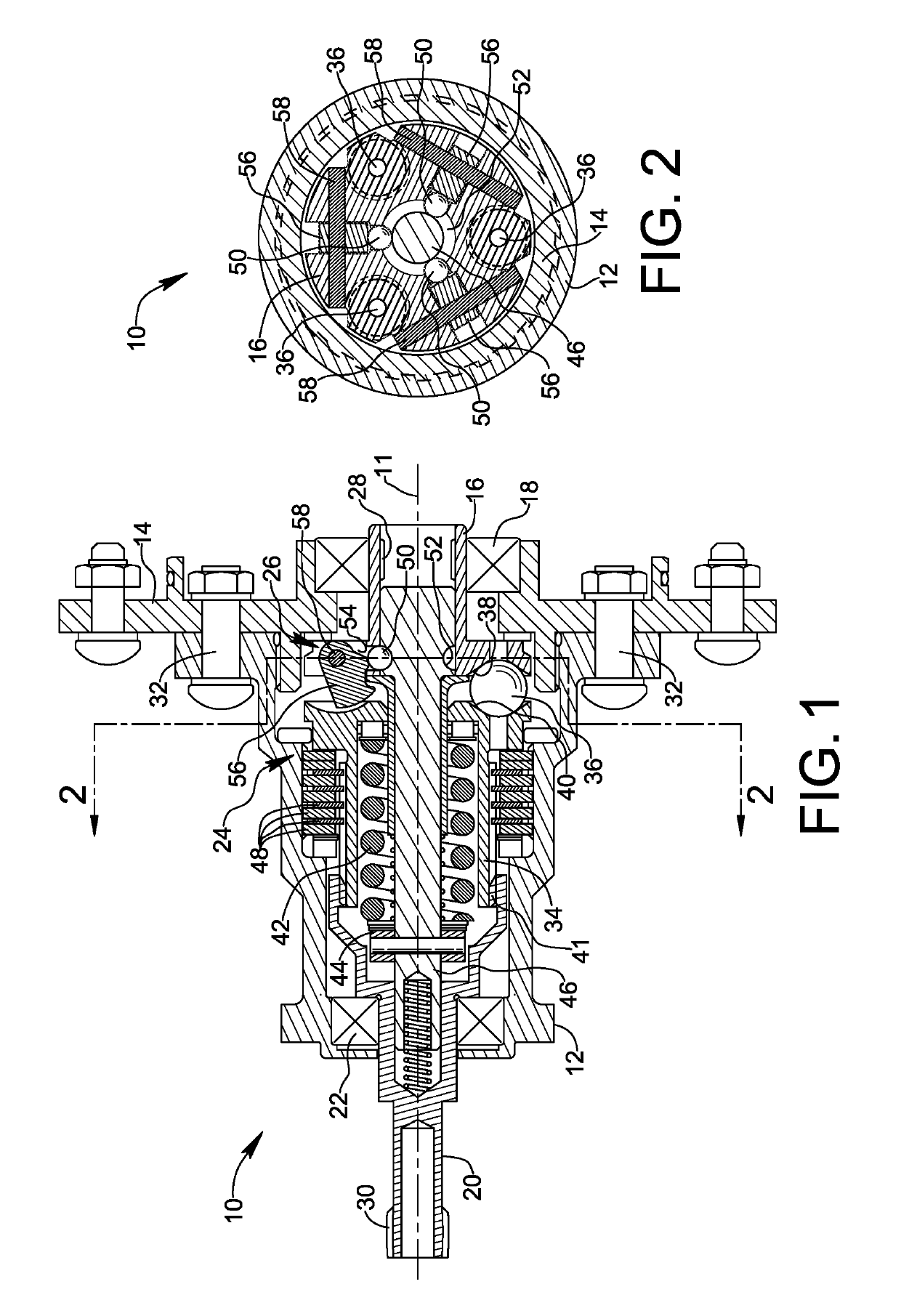
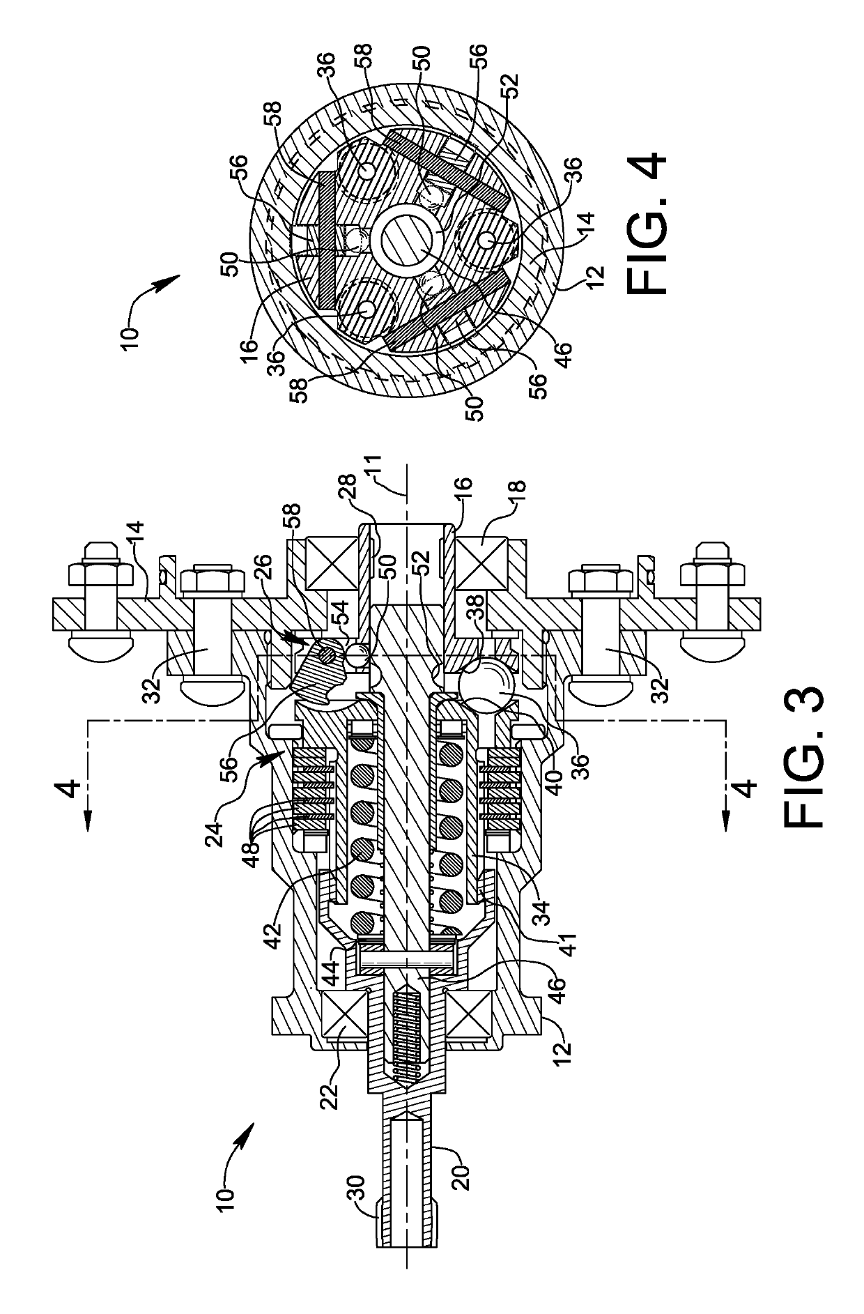
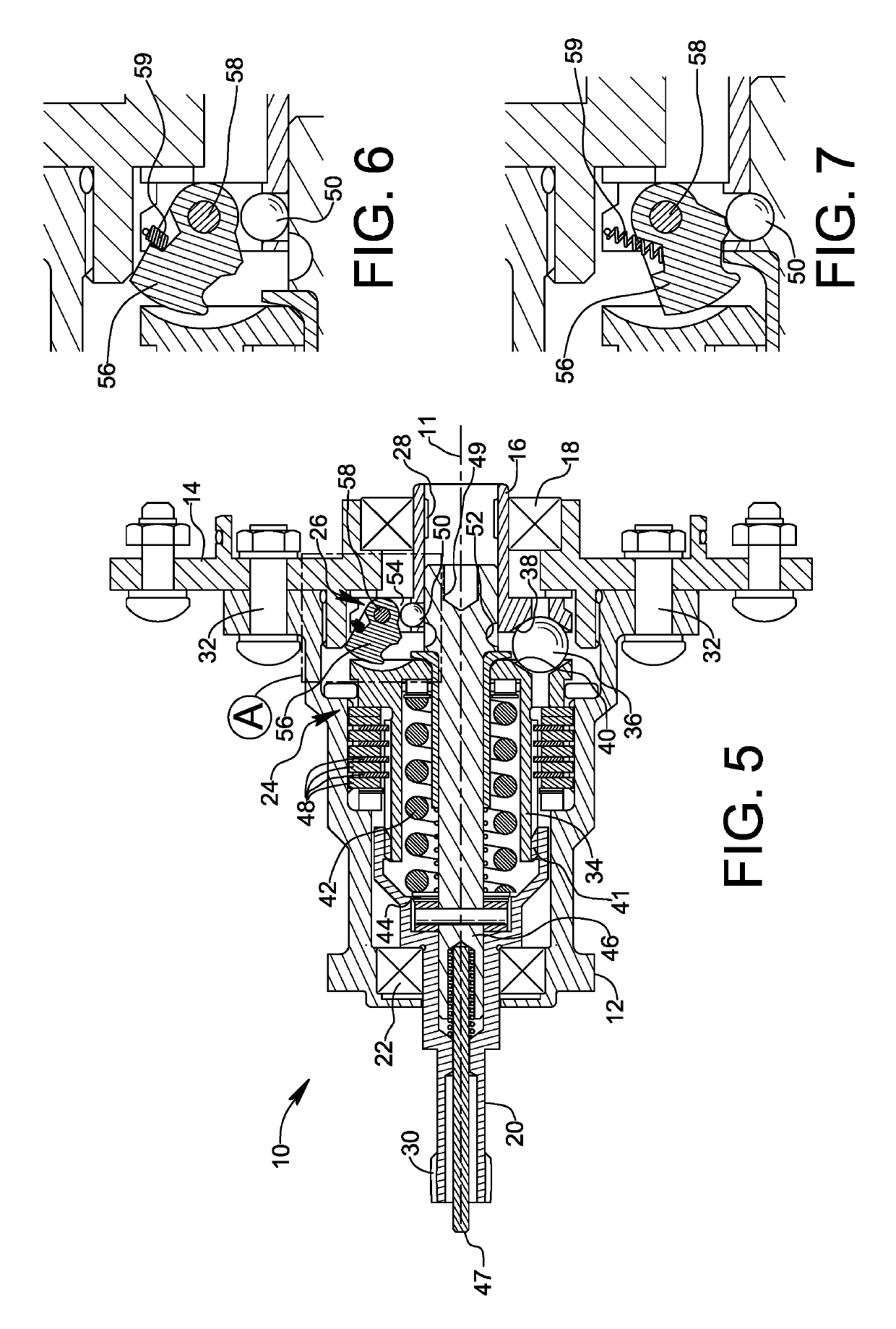
[0023]Reference is made initially to FIGS. 1-4, wherein a torque limiter apparatus formed in accordance with a first embodiment of the invention is shown and identified generally by reference numeral 10. Apparatus 10 comprises a structural ground in the form of housing members 12 and 14, an input element 16 rotatable about a rotational axis 11 relative to the structural ground by virtue of a rotary bearing 18, and an output element 20 rotatable relative to the structural ground by virtue of another rotary bearing 22. Apparatus 10 further comprises a torque limiter 24 and an over-speed governor 26 described in greater detail below. As will be understood, apparatus 10 is useful for connecting a rotational drive member (not shown) to a rotational driven member (not shown) by coupling the drive member to input element 16 and by coupling the driven member to output element 20. Coupling of the drive member to input element 16 may be achieved by a splined connection to a spline 28 of input...


PUM


Abstract

An apparatus for connecting a rotational drive member to a rotational driven member brakes rotation when either the torque transmitted between the members exceeds a predetermined torque limit or the rotational speed of the drive member exceeds a predetermined rotational speed limit. The apparatus includes a torque limiter configured to actuate a braking mechanism or disconnect transmission when the torque limit is exceeded, and an over-speed governor configured to trigger the torque limiter when the rotational speed of the input element exceeds the rotational speed limit. The over-speed governor may trigger the torque limiter by reducing the torque limit of the torque limiter, or by introducing rotational drag in the apparatus to increase transmitted torque.

Description

FIELD OF THE INVENTION[0001]The present invention relates generally to torque limiters for preventing the transmission of torque from a driving element to a torque responsive element when a predetermined torque limit has been reached. More specifically, the present invention relates to a torque limiter configured to lockup when the driving element experiences a rotational over-speed condition.BACKGROUND OF THE INVENTION[0002]Torque limiters are used in aircraft flight control systems to prevent the transmission of excess torque from a drive unit when a flight control surface actuated by the drive unit becomes jammed. Flight control surfaces include, for example, a trailing edge flap on a wing.[0003]A torque limiter commonly includes an input element coupled to an output element through a braking mechanism responsive to an over-torque condition, as may be experienced when the output element is prevented from rotation due to a malfunction. In a well-known arrangement, the braking mech...

Claims


Application Information

Patent Timeline
Patent Type & Authority Patents(United States)
IPC IPC(8): F16D7/02F16D43/21F16D43/22
CPCF16D7/027F16D43/22F16D43/216F16D2043/145F16D43/16F16D43/04F16D43/18F16D43/12
Inventor LARSON, LOWELL VAN LUND
Owner MOOG INC
Learn More