Recessed concrete rail seat assembly

a technology of recessed concrete and rail seats, which is applied in the direction of railway tracks, roads, constructions, etc., can solve the problems of wide gauge and rail seat abrasion on the usa heavy haul railroad track, and achieve the effects of less concrete surface abrasion, and long component service li

Active Publication Date: 2019-08-27
PROGRESS RAIL SERVICES
View PDF14 Cites 0 Cited by
  • Summary
  • Abstract
  • Description
  • Claims
  • Application Information

AI Technical Summary

Benefits of technology

[0014]The interlock feature between the anti-abrasion assembly and the concrete tie also minimizes relative movement between abrasion plate and concrete tie, which results in less concrete surface abrasion. The new fastening system is expected to provide longer component service life and less track maintenance.

Problems solved by technology

Heavy haul railroad track in the USA has been experienced wide gauge and rail seat abrasion due to insufficient lateral and longitudinal support from the side and the bottom of the rail.

Method used


Image

  • Recessed concrete rail seat assembly
  • Recessed concrete rail seat assembly
  • Recessed concrete rail seat assembly

Examples


Embodiment Construction

[0017]A preferred embodiment of the invention will be descried with reference to the drawings in which

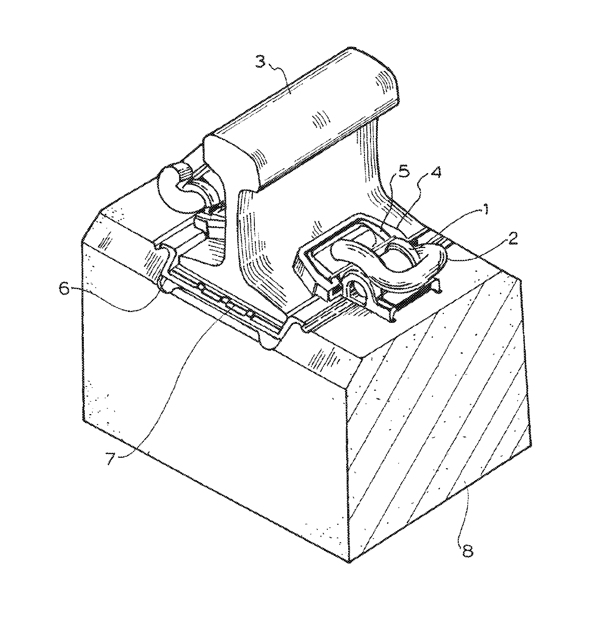
[0018]FIG. 1 shows the complete fastening system assembled in a rail seat;

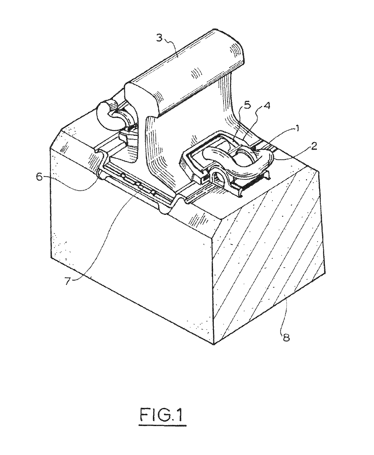
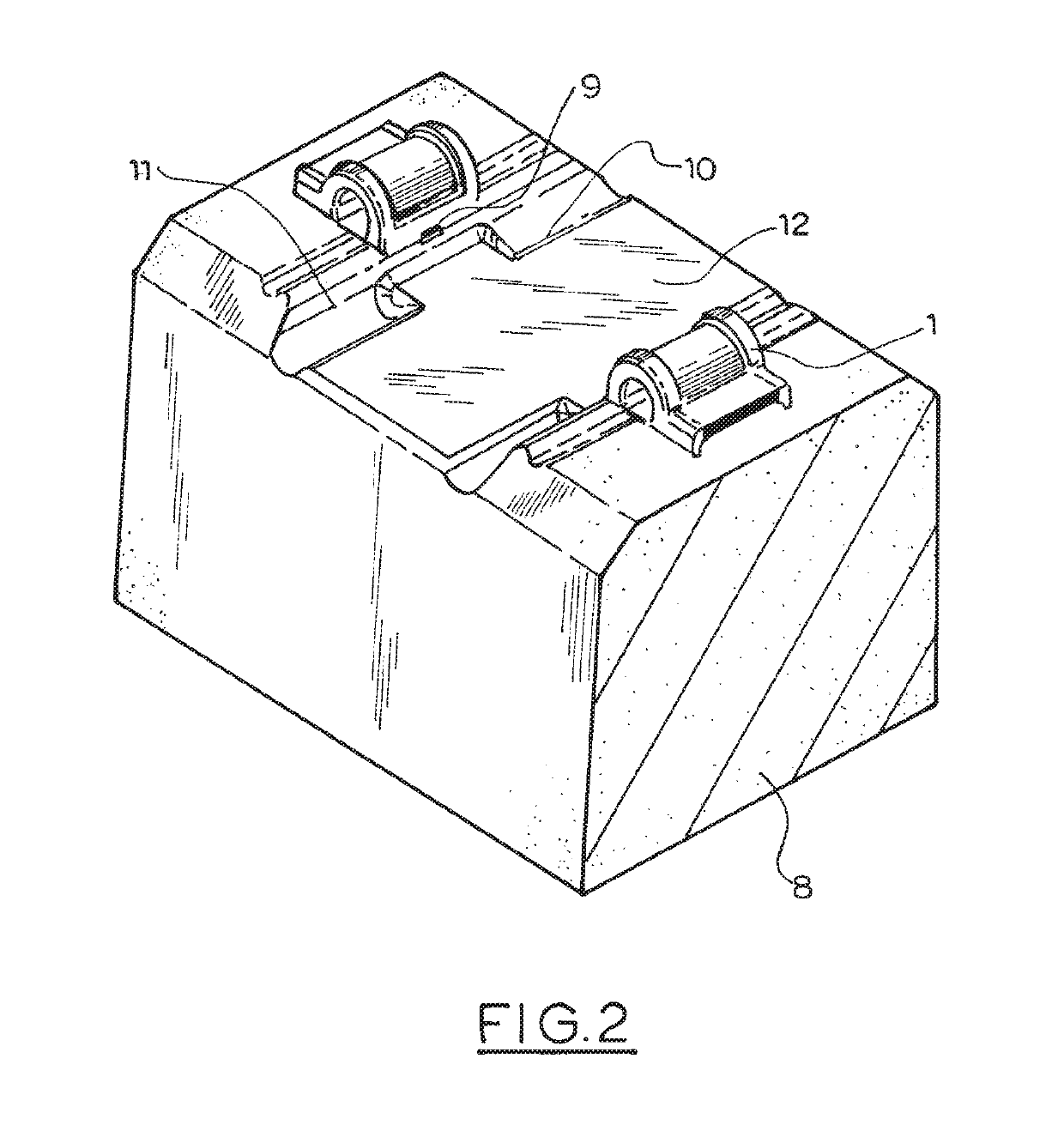
[0019]FIG. 2 shows the concrete tie with a cast in shoulder;

[0020]FIG. 3 shows the anti-abrasion plate assembly pre-assembled in the concrete tie;

[0021]FIG. 4 shows the preferred shoulder of this invention;

[0022]FIG. 5 shows the anti-abrasion plate of this invention;

[0023]FIG. 6 shows the heavy duty toe insulator.

[0024]FIG. 1 shows the complete fastening system assembled in a rail seat section of the concrete tie 8. The rail 3 is supported in the bottom by the rail pad 7 and the anti-abrasion plate 6, supported on the sides by the anti-abrasion plate's side post 18. The rail base is clamped on top by the heavy duty insulator liner 4 and steel insert 5, the clamping force is provided by clip 2. The clip is supported by shoulder 1 which is cast in the concrete tie 8.

[0025]FIG. 2 shows the concrete tie 8 with cas...


PUM


Abstract

A low maintenance rail seat has recess in the concrete tie and an abrasion plate that covers the floor of the recess and its sides parallel to the rail base. The abrasion plate includes ribs which seat in additional recesses in the tie to retard longitudinal movement. The anti-abrasion assembly preferably has four flanges which wrap around the top of concrete tie to prevent dust particles from entering and abrading the concrete rail seat. These flanges also wrap around the support shoulder for additional resistance to longitudinal movement. The components are designed to provide 8.5″ of lateral support along the side of the rail base while the traditional e clip fastener provides only 3″ of lateral support. The interlock feature between the anti-abrasion assembly and the concrete tie also minimizes relative movement between abrasion plate and concrete tie, which results in less concrete surface abrasion.

Description

PRIORITY[0001]Priority is claimed as a national stage application, under 35 U.S.C. § 371, to international patent application No. PCT / US2016 / 026188, filed Apr. 6, 2016, which claims priority to Australian patent application 2015901265, filed Apr. 9, 2015. The disclosures of the aforementioned priority applications are incorporated herein by reference in their entirety.[0002]This invention relates to improvements in rail seat assemblies with concrete ties and cast in support shoulders.BACKGROUND TO THE INVENTION[0003]Heavy haul railroad track in the USA has been experienced wide gauge and rail seat abrasion due to insufficient lateral and longitudinal support from the side and the bottom of the rail. Frequent maintenance is required to keep the track in good condition.[0004]U.S. Pat. No. 4,757,945 discloses a sleeper with a recessed rail seat and further recesses in the rail seat to accommodate the feet of a rail insulator interposed between the shoulder and the rail base.[0005]USA p...

Claims


Application Information

Patent Timeline
Patent Type & Authority Patents(United States)
IPC IPC(8): E01B9/30E01B9/48E01B9/68
CPCE01B9/68E01B9/303E01B2205/00E01B9/483E01B9/685
Inventor NGUYEN, THAIMEDIAVILLA, JOSE RICARDO
Owner PROGRESS RAIL SERVICES
Why Eureka
Try Eureka