Eureka AIR delivers breakthrough ideas for toughest innovation challenges, trusted by R&D personnel around the world.

Bus bar module

a bus bar and module technology, applied in the field of bus bar modules, can solve the problems of reducing the sectional area of the bus bar, and achieve the effects of reducing increasing the accuracy of current measurement, and restraining the influence of a magnetic field

Active Publication Date: 2019-08-27
DENSO CORP
View PDF8 Cites 0 Cited by
  • Summary
  • Abstract
  • Description
  • Claims
  • Application Information

AI Technical Summary

Benefits of technology

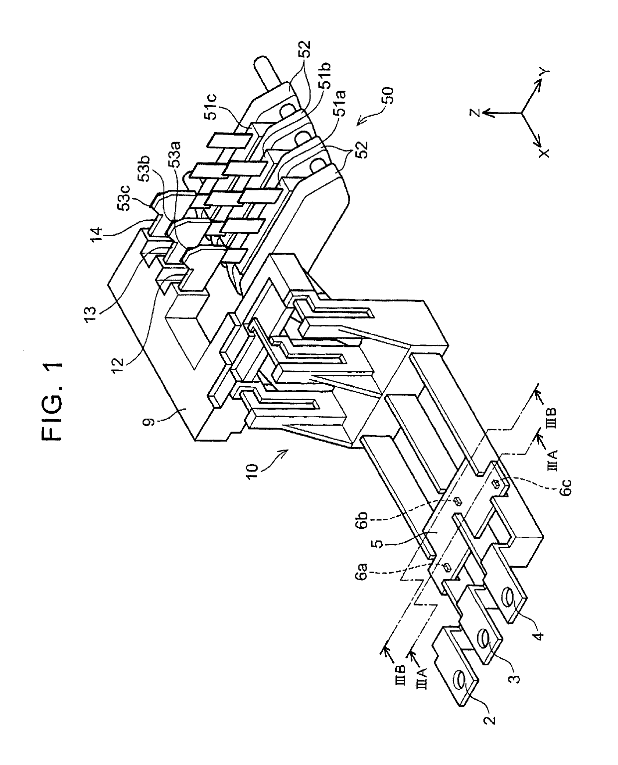
[0010]In a current sensor that does not have a magnetic core, if a magnetoelectric transducer is not provided in an exact position relative to a bus bar, accuracy of current measurement decreases. The present specification provides a bus bar module that improves a conventional technique, restrains the influence of a magnetic field generated from an adjacent bus bar, and increases accuracy of current measurement by accurately securing relative positions of a bus bar and a magnetoelectric transducer.
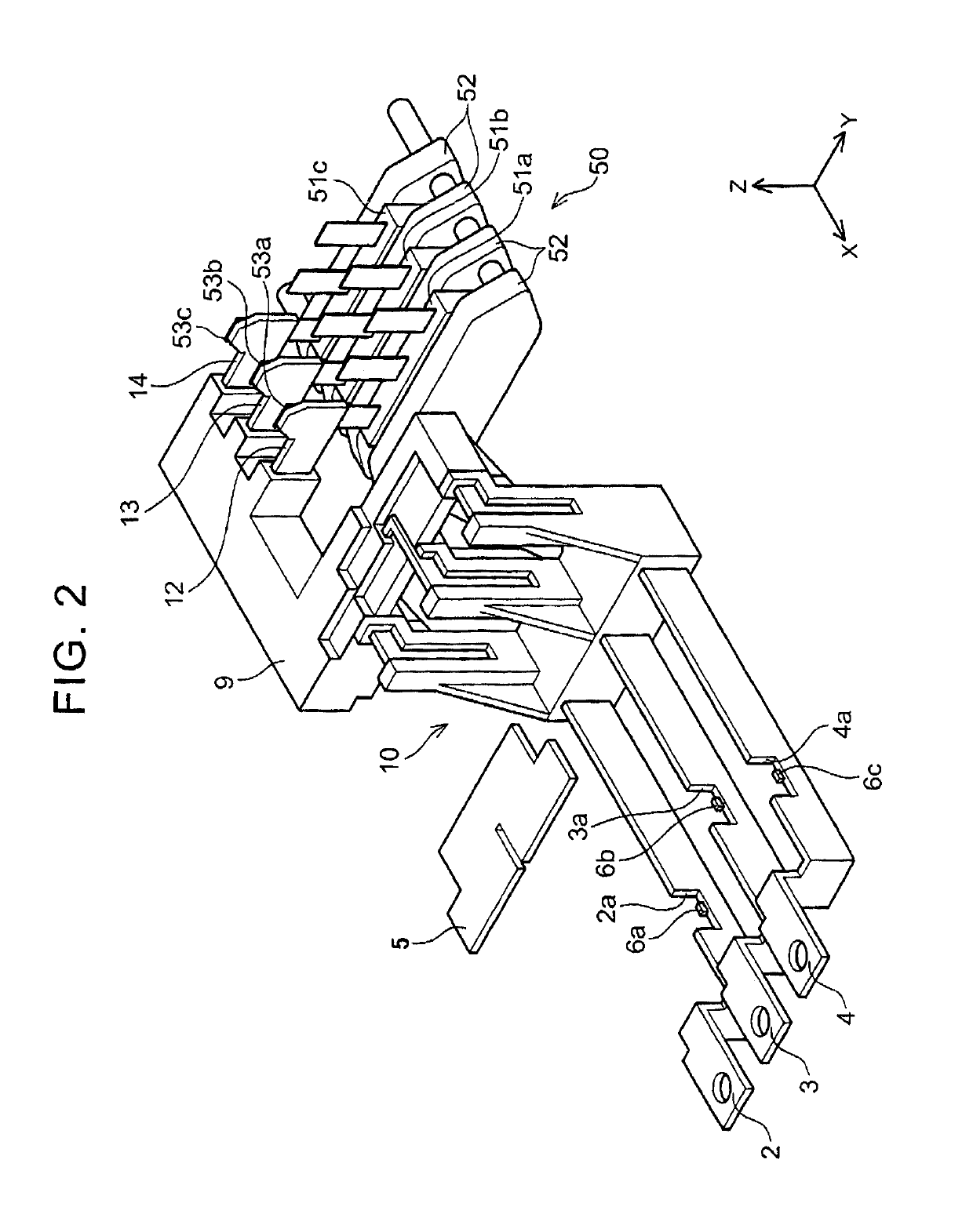
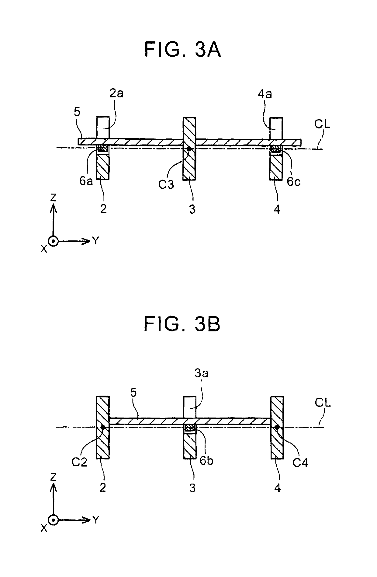
[0012]In the above bus bar module, the substrate secures accurate relative positions of the first bus bar and the second bus bar in terms of two directions. The two directions indicate an extending direction of the bus bars and an aligning direction of the bus bars. Here, the “extending direction” is a longitudinal direction of a bus bar, which is an elongated metal plate (bar), and indicates a direction where a current flows. Further, the “aligning direction” is a direction perpendicular to the extending direction, and indicates a direction where the first bus bar and the second bus bar are aligned. Further, by provided the magnetoelectric transducer in the substrate, accurate relative positions of the magnetoelectric transducer and the bus bar are secured. On that account, current measurement accuracy of the bus bar module is increased. Further, in the bus bar module, one substrate is assembled to a plurality of bus bars, so that relative positions of the plurality of bus bars to the magnetoelectric transducer are determined. Accordingly, with a simple assembly operation of the bus bar module, high relative position accuracy can be obtained.
[0013]Further, the notch reduces the sectional area of the bus bar. When the sectional area of the bus bar is reduced, a current density is increased. It is known that, when the current density is increased, a magnetic flux density caused around the bus bar due to the current is increased. In the above bus bar module, the first bus bar is configured such that a current path is narrowed by the first notch to increase the magnetic flux density, and the second bus bar adjacent thereto is configured such that the second notch is provided at a different position from the first notch in the extending direction. Hereby, the influence (that is, noise) of the magnetic flux generated from the second bus bar is restrained in the first bus bar.

Problems solved by technology

Further, the notch reduces the sectional area of the bus bar.

Method used


Image

  • Bus bar module
  • Bus bar module
  • Bus bar module

Examples


Embodiment Construction

[0031]A first magnetoelectric transducer measures a magnetic flux (magnetic flux density) generated around a first bus bar due to a current flowing through the first bus bar. A magnitude of the magnetic flux density measured by the first magnetoelectric transducer uniquely corresponds to a magnitude of the current flowing through the first bus bar. Accordingly, the magnitude of the current flowing through the first bus bar is obtained from the magnetic flux density measured by the first magnetoelectric transducer. In order to simplify the description as follows, to obtain the magnitude of the current flowing through the first bus bar from the magnetic flux density measured by the first magnetoelectric transducer may be expressed as “the current of the first bus bar is measured by the first magnetoelectric transducer.”

[0032]The magnetic flux density measured by the first magnetoelectric transducer includes a magnetic flux density caused due to a current flowing through a second bus b...


PUM


Abstract

A bus bar module equipped with a current sensor includes a first bus bar, a second bus bar, a substrate, and a first magnetoelectric transducer. The first bus bar has a first notch. The second bus bar has a second notch and is placed in parallel to the first bus bar. The second notch is provided at a position different from the first notch in an extending direction of the first bus bar. The substrate is fitted to both the first notch and the second notch. Further, the substrate is sandwiched between those side surfaces of the first bus bar and the second bus bar which are opposed to each other. The first magnetoelectric transducer is placed inside the first notch and fixed to the substrate.

Description

BACKGROUND OF THE INVENTION[0001]1. Field of the Invention[0002]The present invention relates to a bus bar module including a plurality of bus bars. Particularly, the present invention relates to a bus bar module including a current sensor.[0003]2. Description of Related Art[0004]An electrically-driven vehicle using a heavy-current uses a bus bar module in a power conversion apparatus for outputting electric power to a drive motor. The power conversion apparatus includes an inverter circuit for converting direct-current power of a battery into three-phase alternating current power. Since the power conversion apparatus of the electrically-driven vehicle uses a heavy-current, a bus bar module is used to transmit a three-phase output of the inverter circuit. The bus bar module for transmitting a three-phase output has three bus bars extending in parallel to each other.[0005]The power conversion apparatus often includes a current sensor to monitor a three-phase output current. Since an ...

Claims


Application Information

Patent Timeline
Patent Type & Authority Patents(United States)
IPC IPC(8): G01R15/14H02M7/00G01R15/20H02M1/00
CPCG01R15/148G01R15/207H02M7/003H02M1/0009
Inventor NAKAYAMA, WATARUGOTO, KENJI
Owner DENSO CORP
Why Eureka
Eureka Blog
Learn More