Moveable jaw mounting assembly

a technology for moving jaws and mounting assemblies, which is applied in the direction of grain treatments, etc., can solve the problems of relative complexity of retraction, achieve the effects of simple structure, convenient adjustment of css and/or shims, and minimise stress and load bearing concentration

Inactive Publication Date: 2019-09-03
SANDVIK INTELLECTUAL PROPERTY AB
View PDF28 Cites 0 Cited by
  • Summary
  • Abstract
  • Description
  • Claims
  • Application Information

AI Technical Summary

Benefits of technology

[0010]It is an object of the present invention to provide a robust, reliable and simplified mounting assembly operative to enable convenient adjustment of the CSS and / or shim-setting. It is a further objective to minimise stress and load bearing concentrations on the mounting assembly components where possible.
[0015]Preferably, a longitudinal axis of the mechanical actuator is aligned substantially parallel to a longitudinal axis extending through the toggle unit. This alignment provides for maximum efficiency of the pulling and pushing force imparted by the actuator to the toggle unit as this force is aligned perpendicular to the force transmission wall and somewhat parallel with the crushing force.
[0018]Preferably, the actuator is mounted to the toggle unit at a region of the second toggle end. More preferably the actuator is mounted to the toggle unit via a floating abutment connection between the back end toggle beam and a back end toggle plate. That is, the actuator is not coupled directly to the movable jaw and acts directly on the toggle unit. Due to the relative close proximity mounting of the actuator to the toggle unit, it is possible to use an actuator of compact and robust design. This is advantageous to assist with the overall weight reduction of the jaw crusher and to extend the actuator operational lifetime.
[0025]Preferably, each mechanical actuator is pivotally attached via a mounting to the second toggle end. The attachment of the cylinder rod to the toggle seat is achieved via alignment of the centre of the cylinder rod eye with the pivot line (longitudinal axis of the toggle seat). This concentric alignment minimises stress concentrations and accordingly extends the operational lifetime of the actuator.

Problems solved by technology

However, conventional retraction assemblies that either allow adjustment of the CSS or enable shim-setting modes include relatively complicated retraction actuator and hydraulic jack arrangements that perform separate functions.

Method used


Image

  • Moveable jaw mounting assembly
  • Moveable jaw mounting assembly
  • Moveable jaw mounting assembly

Examples


Embodiment Construction

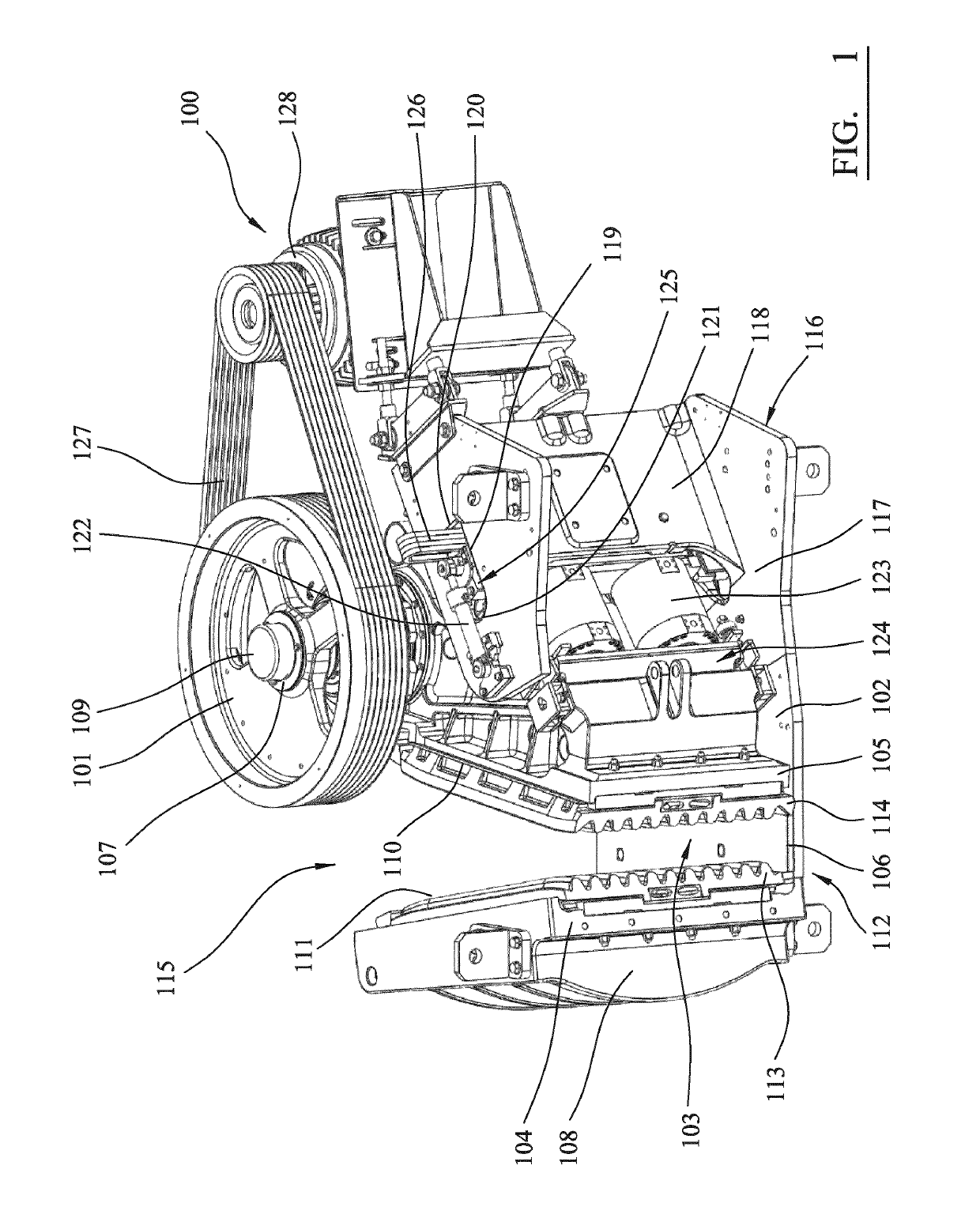
[0034]Referring to FIG. 1, a jaw crusher 100 comprises a main frame 102 upon which is mounted a moveable jaw 105 and a substantially fixed jaw 104. The movable jaw 105 is mounted eccentrically at a rotatable shaft 107 (extending from underneath an end cap 109) and is positioned separated and opposed to fixed jaw 104. The orientation of fixed jaw 104 and movable jaw 105 relative to one another is convergent along their respective lengths such that a separation distance between a crushing face 111 of fixed jaw 104 and a corresponding crushing face 110 of movable jaw 105 decreases in the downward lengthwise direction. A suitable wear plate 113 is removably attached to crushing face 111 of fixed jaw 104 and a corresponding wear plate 114 is removably attached to crushing face 110 of movable jaw 105. Main frame 102 comprises two opposed frame walls that support the front frame end 108, which is aligned substantially perpendicular to frame walls 102. The side walls extend either side of f...


PUM


Abstract

A movable jaw mounting assembly to provide adjustment of the close side setting (CSS) of a movable jaw and to act as a retraction assembly or assist with retraction. The assembly includes a pair of linear actuators that are coupled between the back frame end and a region of the toggle unit so as to move the toggle unit towards and away from the back frame end to allow insertion and removal of spacers and / or shims.

Description

RELATED APPLICATION DATA[0001]This application is a § 371 National Stage Application of PCT International Application No. PCT / EP2013 / 075379 filed Dec. 3, 2013 claiming priority of EP Application No. 13150629.7, filed Jan. 9, 2013.FIELD OF INVENTION[0002]The present invention relates to a mounting assembly for a moveable jaw of a jaw crusher, and in particular although not exclusively, to a moveable jaw retraction assembly configured to displace a toggle unit formed from a force transmission wall to allow adjustment of a working separation distance between the moveable jaw and a stationary jaw.BACKGROUND ART[0003]Jaw crusher units typically comprise a fixed jaw and a movable jaw that together define a crushing zone. A drive mechanism is operative to rock the movable jaw back and forth in order to crush material in the crushing zone.[0004]The crushing zone is generally convergent towards its lower discharge end so that crushable material fed to the upper and wider end of the zone is c...

Claims


Application Information

Patent Timeline
Patent Type & Authority Patents(United States)
IPC IPC(8): B02C1/00B02C1/02B02C1/06
CPCB02C1/02B02C1/025B02C1/06
Inventor SVENSSON, JOHANLINDBERG, MARTEN
Owner SANDVIK INTELLECTUAL PROPERTY AB
Why Eureka
Try Eureka