Portable light tower

a technology of light towers and trailers, applied in the direction of wheel supports, lighting and heating equipment, lighting support devices, etc., can solve the problems of affecting shipping and storage, reducing the service life of light towers, so as to achieve the effect of reducing the weight of a conventional bedpla

Active Publication Date: 2019-09-03
KENNEDY GINO
View PDF26 Cites 2 Cited by
  • Summary
  • Abstract
  • Description
  • Claims
  • Application Information

AI Technical Summary

Benefits of technology

[0007]A compact portable light tower employing a scissors lift mechanism to raise a set of bar lights from a housing having a height of about 28″ and a length of about 60″, to an extended height of about 360″. The scissors lift is extended and retracted by use of a linear actuator. Batteries or an engine / generator assembly is employed for operation of the actuator and light bar. The engine / generator assembly eliminates the weight of a conventional bedplate by couplings
[0011]Still another objective of the instant invention is to provide a portable tower trailer having a light tower including a generator attached to an engine to eliminate the weight of a conventional bed plate.
[0013]It is an objective of the instant invention to provide a portable tower trailer having a light tower that eliminates the need for placing multiple light towers on a single large common trailer, such as a flatbed, where space is limited to the length and width of the flatbed. Multiple light towers can be towed on the portable tower trailer by a vehicle in a stackable or nesting fashion.

Problems solved by technology

Typically the mast is a telescoping pole that is limited in height extension by the length of individual mast sections which must fit within adjoining mast sections leading to more costly designs due to the need for individual parts that are not exchangeable.
Present light towers lack compact storage features which can affect shipping as well as storage.
Placing multiple light towers on a single large common trailer, such as a flatbed, is limited to the length and width of the flatbed.
Furthermore, placing multiple light towers mounted on a flatbed or on a single large common trailer is limited since all known prior art light towers have no provision for nesting or stacking.
Existing light towers lack compact storage features which can also cause problems in storage.

Method used


Image

  • Portable light tower
  • Portable light tower
  • Portable light tower

Examples


Embodiment Construction

[0028]While the present invention is susceptible of embodiment in various forms, there is shown in the drawings and will hereinafter be described a presently preferred, albeit not limiting, embodiment with the understanding that the present disclosure is to be considered an exemplification of the present invention and is not intended to limit the invention to the specific embodiments illustrated.

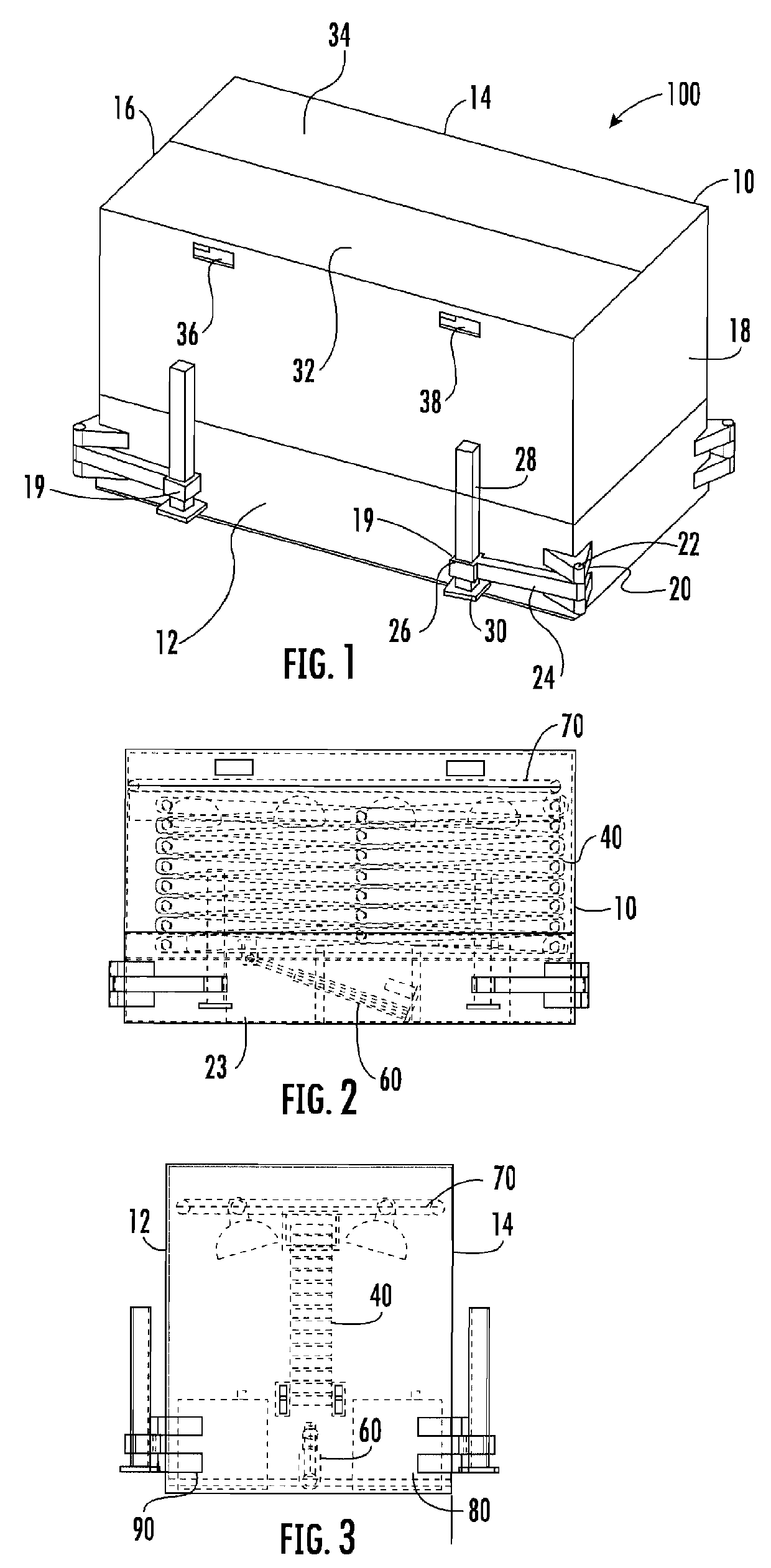
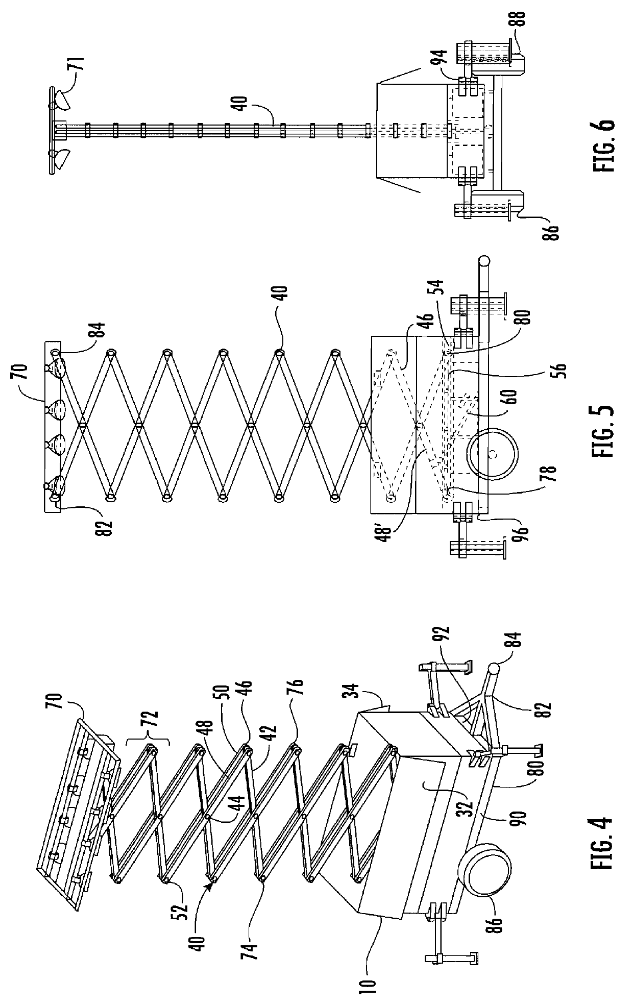
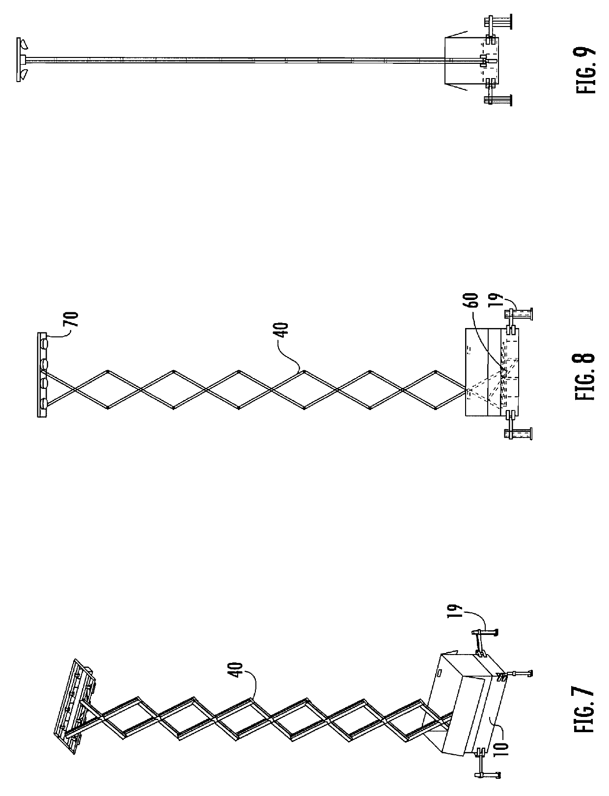
[0029]Referring now to Figures, set forth is a portable lift housing 10 defined by a left side wall 12, a right side wall 14, a first end wall 16 and a second end wall 18. Along the corners of the housing are located outriggers 19 for use in lifting the housing 10 off the ground, as well as for use in stabilizing the housing 10 for uneven ground placement. Each outrigger 19 has a base 20 secured to the housing 10. A displacement arm 200 is pivotally coupled to the base 20 by a pivot pin 22. A distal end of each outrigger 19 includes a square shaped aperture 26 allowing the slidable extension...


PUM


Abstract

Disclosed is a compact portable light tower that can be stacked or nested. The light tower employs a scissors lift mechanism to raise a set of bar lights from a housing having a height of about 28'' and a length of about 60'', to an extended height of about 360''. The scissors lift is extended and retracted by use of a linear actuator. Batteries or an engine / generator assembly is employed for operation of the actuator and light bar. The housing can be stacked for ease of storage and transportation. Outriggers provide stabilization of ground engagement.

Description

PRIORITY CLAIM[0001]In accordance with 37 C.F.R. 1.76, a claim of priority is included in an Application Data Sheet filed concurrently herewith. Accordingly, the present invention claims priority to U.S. Provisional Patent Application No. 62 / 468,790 entitled “Portable Light Tower”, filed on Mar. 8, 2017 and U.S. Provisional Patent Application No. 62 / 468,780 entitled “Light Tower with Vertical Actuator”, filed on Mar. 8, 2017, the contents of which is incorporated herein by reference in its entirety.FIELD OF THE INVENTION[0002]The instant invention relates to portable light towers and more specifically to a light tower employing a scissors lift for lighting.BACKGROUND OF THE INVENTION[0003]Portable towers typically employ a telescoping mask which extends upwardly from a portable base to support a bank of lights overhead to temporarily illuminate an area in low lighting conditions. Typically the area to be illuminated lacks electrical power wherein the portable light towers have their...

Claims


Application Information

Patent Timeline
Patent Type & Authority Patents(United States)
IPC IPC(8): F21V21/22F21V21/24F21V21/06F21V21/26B60P3/18F21L13/00F21W131/10
CPCF21V21/06F21V21/22F21V21/24F21V21/26F21W2131/10B60P3/18F21L13/00F21L14/04
Inventor KENNEDY, GINO
Owner KENNEDY GINO
Why Eureka
Try Eureka