Manufacturing method for composite material structural component for aircraft and its structural component

a manufacturing method and composite material technology, applied in the field of manufacturing methods of composite material structural components for aircraft and its structural components, can solve the problems of expensive autoclaves and ovens, needless increase in etc., and achieve the effect of reducing the number of conductive members included in the structural components, and reducing the weight of aircraft bodies

Inactive Publication Date: 2009-04-30
SHIN MEIWA IND CO LTD
View PDF4 Cites 20 Cited by
  • Summary
  • Abstract
  • Description
  • Claims
  • Application Information

AI Technical Summary

Benefits of technology

[0022]Still another aspect of the present invention is directed to a structural component made of a composite material and constituting part of an aircraft. Furthermore, the structural component includes a composite part made of the composite material and a conductor part made of a conductive material, and the conductor part serves as a part that gives to the aircraft at least two of a lightning strike protection function, an anti-icing and deicing function, an electromagnetic interference shielding function, a function of a heating element for formation of the composite material in manufacturing the structural component and a function of a heating element for assembly of the structural component in manufacturing the structural component. In other words, the conductor part has at least two functions, which correspondingly

Problems solved by technology

Thus, the structural component includes an unnecessary member for the product.
This means needless

Method used


Image

  • Manufacturing method for composite material structural component for aircraft and its structural component
  • Manufacturing method for composite material structural component for aircraft and its structural component
  • Manufacturing method for composite material structural component for aircraft and its structural component

Examples


embodiment 1

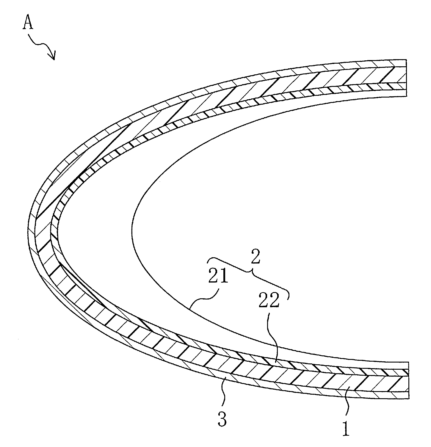
[0027]FIG. 1 shows an aircraft structural component A according to Embodiment 1 of the present invention. The structural component A is a structural component constituting the leading edge of a wing in this embodiment. However, the structural component A according to the present invention is not limited to the above structural component. For easy understanding, FIG. 1 expresses the thicknesses of layers constituting the cross section of the structural component A in a different manner from their actual thicknesses.

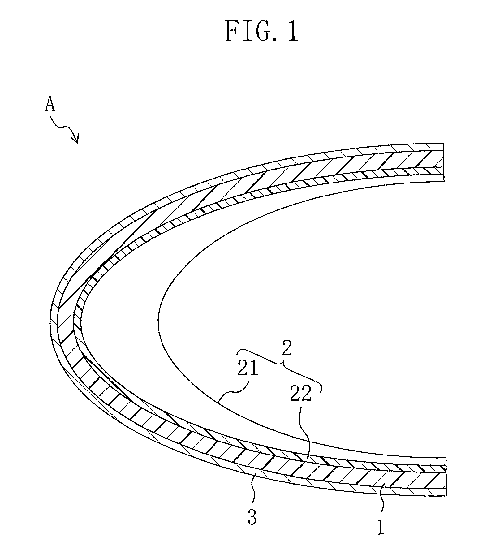
[0028]As shown in FIG. 2, the structural component A includes an outer plate 1 having a cross section curved substantially in the shape of the letter U and extending in the direction of the wing span, and a plurality of ribs 2 joined to the inner surface of the outer plate 1 at specified intervals in the direction of the wing span. Although not shown, beads may be formed on the inner surface of the outer plate 1.

[0029]Each rib 2 includes an arcuate web 21 curved around the...

embodiment 2

[0037]FIG. 3 shows an aircraft structural component B (the leading edge of a wing) according to Embodiment 2 of the present invention. This structural component B is different from the structural component A shown in FIG. 1 in that a metal mesh 4 is interposed between the flanges 22 of ribs 2 and the inner surface of an outer plate 1. The metal mesh 4 functions as a heat source for anti-icing and deicing in the aircraft.

[0038]In manufacturing the structural component B according to Embodiment 2, in Process P3 of the manufacturing procedure shown in FIG. 2, the metal mesh 4 is attached to the joint surfaces of the flanges 22 of the ribs 2 and the ribs 2 are pressed against the predetermined attachment points of the outer plate 1 while the flanges 22 are heated by conduction of electricity to the metal mesh 4, whereby the ribs 2 and the outer plate 1 are joined. In this case, electricity may be or may not be conducted to the metal mesh 3 attached to the outer plate 1. Processes P1 and...


PUM

PropertyMeasurementUnit
Heataaaaaaaaaa

Abstract

A method for manufacturing a structural component includes a first step of attaching at least one conductive member to a surface of a base material made of a composite material and a second step of forming the base material by conducting electricity to part or the whole of the conductive member to generate heat and/or making an assembly of the structural component by conducting electricity to part or the whole of the conductive member to generate heat. Part or the whole of the conductive member contained in the structural component produced in the first and second steps serves as a member giving to the aircraft at least one of a lightning strike protection function, an anti-icing and deicing function and an electromagnetic interference shielding function.

Description

BACKGROUND OF THE INVENTION[0001](a) Field of the Invention[0002]This invention relates to methods for manufacturing a composite material structural component constituting part of an aircraft and to composite material structural components for aircraft.[0003](b) Description of the Related Art[0004]The bodies of aircraft in flight, particularly, the leading edges of their wings, are often ice-coated. Such icing impairs the aerodynamics of aircraft. To cope with this, a technique is conventionally known in which an electric heater or a heat source using exhaust heat from the engine is attached to a part of the outer surface of a structural component of the aircraft likely to be ice-coated (see, for example, WO99 / 15405).[0005]As disclosed also in the above gazette, composite materials have been recently used as structural components of aircraft. Such a composite material structural component, particularly its portions likely to be struck by lightning, such as wing leading edges, must h...

Claims


Application Information

Patent Timeline
IPC IPC(8): B29C51/00B29C65/34B64C7/00
CPCB29C35/0272Y10T156/1043B29C53/84B29C65/344B29C66/1122B29C66/131B29C66/301B29C66/43421B29C66/43441B29C66/474B29C66/532B29C66/721B29K2101/10B29K2101/12B29K2105/206B29K2305/02B29K2305/10B29L2009/003B29L2031/3085B64C3/28B64D15/12B64D45/02B64D15/00B29C65/3476B29C66/543B29C53/04B29C66/7392B29C66/7394B29C66/73921B29C66/61
Inventor HASEGAWA, KENICHIIKUYAMA, TOHRUIKEDA, MASAHIKOKOCHO, TAKUJI
Owner SHIN MEIWA IND CO LTD
Why Eureka
Try Eureka