Cannulated bone screw

a cannulated bone screw and screw technology, applied in the direction of internal osteosynthesis, fasteners, osteosynthesis devices, etc., can solve the problems of no longer being able to remove, and being unable to remove, so as to reduce the removal torque, increase the retention force, and avoid further damage to the bone structure

Active Publication Date: 2019-09-10
ARTHREX
View PDF26 Cites 22 Cited by
  • Summary
  • Abstract
  • Description
  • Claims
  • Application Information

AI Technical Summary

Benefits of technology

[0013]The embodiments of this disclosure are based on the object of providing a bone screw, which has a channel or lumen for the delivery of a material like medication, therapeutic fluid, or any kind of bone cement or strengthening material. The bone screw should provide an increased retention force and a decreased removal torque, which allows a removal of the screw without further damaging the bone structure. Particularly, removal of the screw should be possible after the screw has been fixed to a bone by injecting cement or a similar material through the screw into the bone or after ingrowth of bone into the screw. Another object is to provide a bone screw, which allows a selective delivery of material at selected positions of the screw. For simplifying the selective application, a specific tool is provided. Another problem to be solved is to improve a method for fastening a bone plate to a bone and / or to reinforce a bone by using a bone screw.
[0015]Next to the proximal section is a center section. The center section has a roughly cylindrical shape and includes a second thread. The diameter of the center section is smaller than the diameter of the proximal threaded section. The pitch of the second outer thread of the center section is larger than the pitch of the first outer thread of the proximal threaded section. This difference in pitches allows for tightly fixing a bone plate to a bone or for tying at least two bone fragments together. Alternatively, both pitches may be similar. At the distal side of the second outer thread, there may be at least one cutout for simplifying cutting of the outer thread into the bone. The center section may bear at least one or a plurality of sideward holes, which allow the flow of material from the channel or lumen into the bone.
[0018]The side openings, which are provided in the center section and / or distal section, are provided by pairs resulting in through-holes through the screw. Therefore, two side openings are oriented at a 180° angle with respect to each other in a plane perpendicular to the center axis of the screw. In an alternative embodiment, there may be three or more side openings in the same plane. At least one opening has an elongated shape with respect to the center axis. The at least one opening may have an elliptical shape. Due to the larger extension or size of the opening parallel to the center axis, a larger total cross section of the opening can be achieved without significantly weakening the structure of the screw. There may be at least one cutting edge at at least one of the side openings. This cutting edge allows cutting of the material or bone cement when removing the screw by rotating counter-clockwise. The angle of the cutting edge is, in one embodiment, less than 90°. At least one of the side openings has a conical shape with increasing diameter towards the outside of the screw. This allows to form a cutting edge and to further increase the cross section for delivery of material into the bone. Here, the term cross section relates to the cross section available for delivery of material.
[0020]A further embodiment relates to a tool, such as a sleeve, which allows selective delivery of material into the bone surrounding the screw. The tool has a hollow shaft and a cylindrical shaft defining an inner channel for delivery of material. The outer diameter of the sleeve is adapted to fit into the channel of the bone screw. The sleeve may be inserted into different positions, which are in proximity to the distal opening or to any specific side opening to allow selective delivery of material into the surrounding bone. For precise adjustment of the insertion depth of the sleeve into the bone screw, there may be markers at the outside of the sleeve. There may be any other measuring tool for indicating the depth and / or the position of the sleeve inserted into the bone screw. The markers indicate the positions of the sleeve close to specific openings for delivering material through these openings. As there may be two openings at opposite sides of the lumen of the bone screw, the cross-section pointing outwards into the bone through the side opening is larger than the cross-section through the lumen of the bone screw. This will result in a significantly larger side flow, sideward through the side openings compared to the center flow through the remaining channel of the bone screw. This allows selective application of material to the bone. For example, material may be supplied through openings in the center section without filling the openings in the distal section. This allows the application of bone cement where needed. Such a selective application of bone cement simplifies later removal of the screw.

Problems solved by technology

After the bone has grown into the structure of the screw, removal is impossible.
If cement has been introduced into the screw, removal is no longer possible.
Once cement has been introduced into the screw, removal is no longer possible.
Another problem to be solved is to improve a method for fastening a bone plate to a bone and / or to reinforce a bone by using a bone screw.
It may be unthreaded.

Method used


Image

  • Cannulated bone screw
  • Cannulated bone screw
  • Cannulated bone screw

Examples


Embodiment Construction

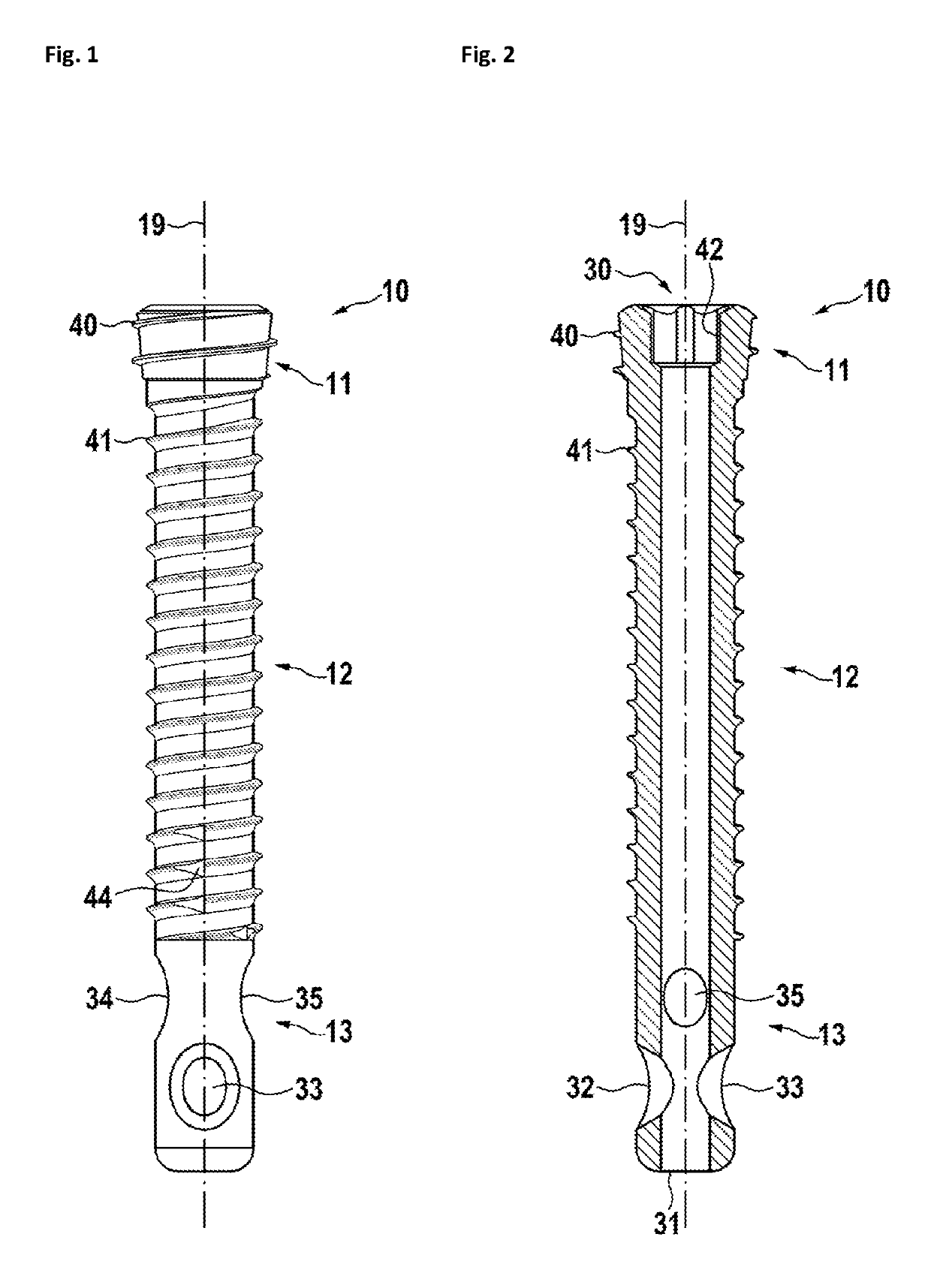
[0040]In FIG. 1, a first embodiment of a bone screw 10 is shown. The bone screw 10 has a threaded proximal section 11, a center section 12, and a distal section 13. The bone screw 10 further has a hollow channel 30 from the proximal section 11 through the distal section 13, defining a center axis 19. The proximal section 11 is approximately cylindrical shaped. It may also have a conical shape to simplify insertion. The proximal section 11 has a first outer thread 40, which is designed to interface with a bone plate 150 as shown in FIG. 16. The center section 12 has a cylindrical shape and is at least partially threaded with a second outer thread 41. The second outer thread 41 may have at least one cutout 44 to improve cutting of the outer thread into the bone material when inserting the screw. The pitch of the first outer thread 40 is less than the pitch of the second outer thread 41 to allow pressing of a bone plate 150 interfacing with the first outer thread 40 to a bone interfaci...


PUM


Abstract

An exemplary bone screw includes a proximal section including a first outer thread, a center section including a second outer thread, an unthreaded distal section on an opposite side of the center section from the proximal section, a channel extending from the proximal section to a distal opening of the unthreaded distal section, and at least one side opening extending from the channel to an outer surface of the unthreaded distal section. In some embodiments, the at least one side opening includes a cutting edge configured to cut a material as the bone screw is rotated in a direction for removing the bone screw. In other embodiments, the side opening is formed in at least one of the center section and the unthreaded distal section and includes a diameter that increases in a direction from the channel toward an outer surface of the center section or the unthread distal section. The exemplary bone screws may be used to treat bone fractures with or without a bone plate.

Description

CROSS-REFERENCE TO RELATED APPLICATIONS[0001]This application is a continuation of pending International Application No. PCT / EP2014 / 071458, filed on Oct. 7, 2014, which designates the United States and claims priority to European Application No. 13187609.6, filed on Oct. 7, 2013.[0002]The entire disclosures of all of the above priority applications are incorporated herein by reference.BACKGROUND[0003]1. Field of the Disclosure[0004]The disclosure relates to orthopedic devices used to reinforce bones in mammals and to a method of treating a humerus fracture. It specifically relates to cannulated bone screws and a method for using them.[0005]2. Description of Relevant Art[0006]Bone screws are used to reinforce bones by connecting at least two sections of a bone and / or by holding bone plates or other parts to a bone. It is often desirable to deliver medication and / or reinforcing material into the bone. A reinforcing material may be any kind of bone cement or bone graft or any other sim...

Claims


Application Information

Patent Timeline
Patent Type & Authority Patents(United States)
IPC IPC(8): A61B17/86A61B17/88
CPCA61B17/864A61B17/863A61B17/8635A61B2017/8655A61B17/8605A61B17/8805
Inventor HIENTZSCH, MARCUSMICHEL, GERLINDESCHEIBEL, MARKUS
Owner ARTHREX
Why Eureka
Try Eureka