Buried pipe lifting device and method

a lifting device and buried pipe technology, applied in the direction of lifting devices, soil shifting machines/dredgers, constructions, etc., can solve the problems of sewer backup, debris in the pipe, sewer sag, etc., and achieve precise staged movement of sections and eliminate the effect of underground utility sag

Active Publication Date: 2019-09-10
THE TROUT GROUP INC
View PDF16 Cites 1 Cited by
  • Summary
  • Abstract
  • Description
  • Claims
  • Application Information

AI Technical Summary

Benefits of technology

[0013]An advantage of the present invention is that the sag of an underground utility can be eliminated without excavating the utility.
[0014]Another advantage is that the present invention allows for a precise staged movement of the sections of the utility.

Problems solved by technology

Sags are typically a problem when they are severe enough to cause debris to settle in the pipe.
The reduced velocity of liquids allows the belly area to collect solids, eventually obstructing the line, resulting in sewer backups.
This repair is only temporary since the gelatinous material is not dimensionally stabile and often requires later replacement.
The grout material is not capable of stabilizing the ground around the pipe even if the entire annular space is filled with the gelatinous grout.
The lack of stability and support can result in additional stress on the pipe structure, with eventual degradation of the pipe and resulting water infiltration.
This sort of in situ repair deals with leaks, but fails to address dips or sags in the pipeline.
Injection of expanding closed cell foams and cementitious grout has been used to level or reinforce pipe sections; however, there can be a migration of the foam or grout into the pipe joint that, if left in place, can cause an occlusion or blockage.
However, these devices cannot lift a utility to an original elevation but rather immobilize the utility from further settlement.
Presently, there is no known mechanical device for the raising of below grade utilities which can be operated for the use of utility raising without excavation.
Cementitious grouting is primarily limited to exterior uses due to the nature of the work.
However, with both techniques the amount of achievable lift is dependent upon soil type, age of the pipeline and the amount of settlement.

Method used


Image

  • Buried pipe lifting device and method
  • Buried pipe lifting device and method
  • Buried pipe lifting device and method

Examples


Embodiment Construction

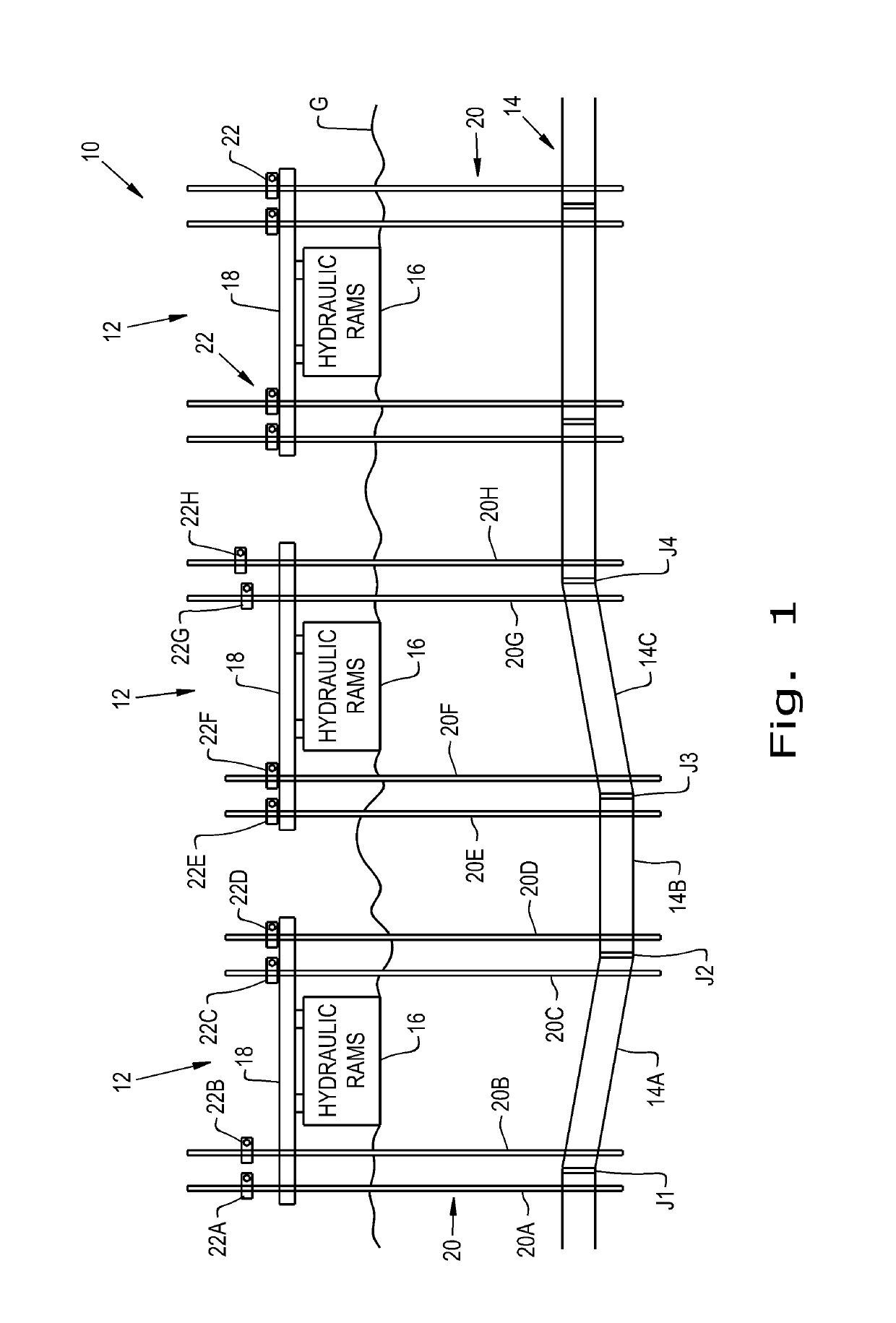
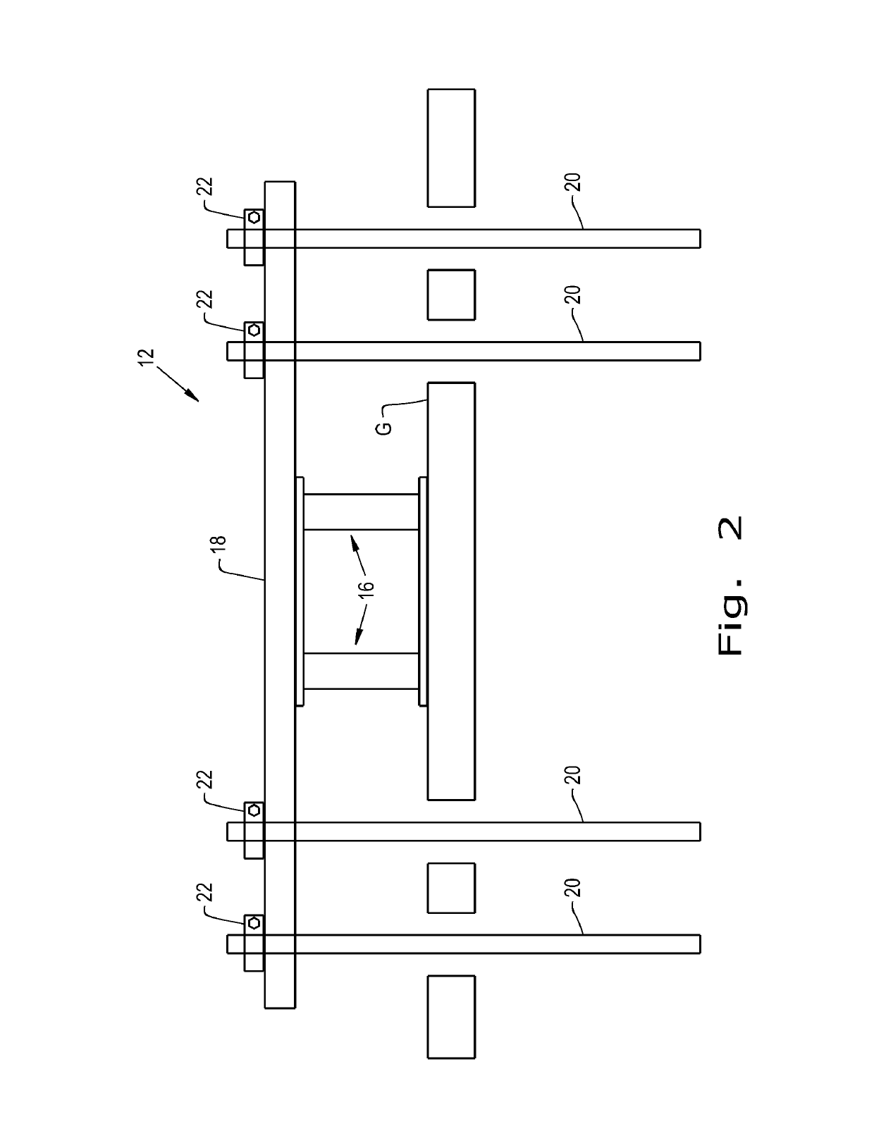
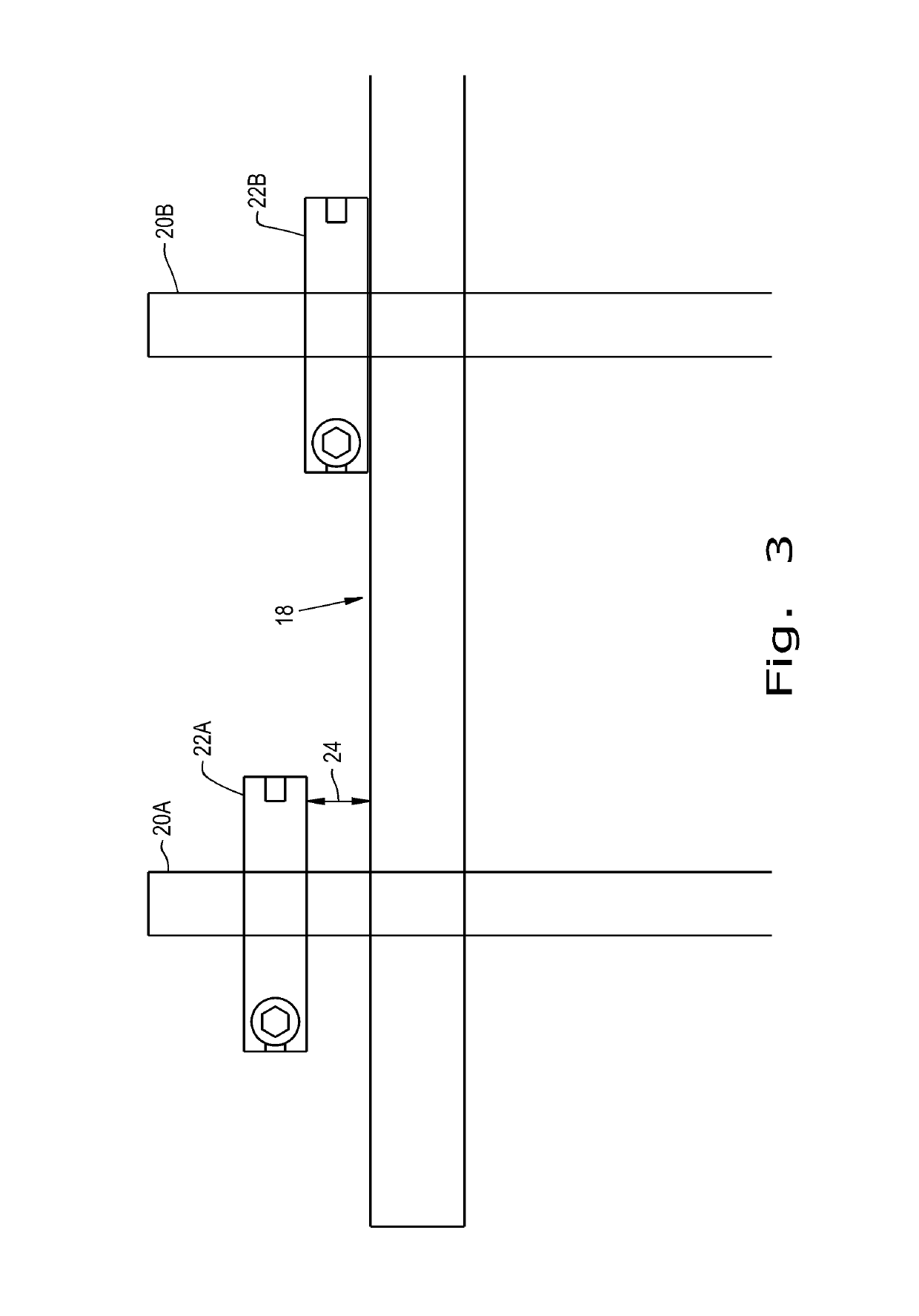
[0025]Referring now to the drawings, and more particularly to FIG. 1, there is shown a system 10 for the in situ relocation of a buried pipe 14. There are shown three underground utility in situ relocation mechanisms 12 each having hydraulic rams 16 also referred to as a lifting device 16, a beam 18, lifting members 20 and lifting collars 22.

[0026]Three pipe segments are identified as segments 14A, 14B, and 14C with joints J1, J2, J3 and J4 of the segments identifying where each segment 14A, 14B, and 14C is coupled to an adjacent pipe segment. Pipes 14 once installed sometimes develop sags or what is also referred to as a belly, which is illustrated by segments 14A, 14B, and 14C, in perhaps a somewhat exaggerated manner, to illustrate the problem that system 10 corrects.

[0027]A survey of the condition of pipe 14 may reveal the location of the sage of pipe segments 14A, 14B, and 14C as well as the locations of joints J1, J2, J3 and J4. Such a survey, perhaps with a sensor package ins...


PUM


Abstract

A method for in situ relocation of an underground utility including the steps of inserting, extending, raising and continuing to raise. The inserting step is carried out by the inserting of at least one lifting member down into the ground alongside the underground utility. The extending step extends a lifting bracket from the at least one lifting member. The raising step raises the lifting member causing the lifting bracket to engage a portion of the underground utility. The continuing step continues to raise the lifting member until the underground utility reaches a predetermined position.

Description

BACKGROUND OF THE INVENTION1. Field of the Invention[0001]The present invention relates generally to the repair of underground utilities, and more particularly to equipment that is used to modify the positioning of underground pipe.2. Description of the Related Art[0002]It is generally known that sewer lines should be constructed with a minimum fall of ¼ inch per 1 foot of pipe. This allows wastewater to continue flowing via gravity through the pipe while minimizing any deposit of debris. When pipes have sags, or low spots in the pipe, also known as “belly”, that don't meet this minimum fall, debris can settle into the low spots. Sags are typically a problem when they are severe enough to cause debris to settle in the pipe. The sag or belly is where the sewer pipe has lost a continuous slope on its way to its destination, and where the rate at which liquids travel through it is significantly reduced. The reduced velocity of liquids allows the belly area to collect solids, eventually...

Claims


Application Information

Patent Timeline
Patent Type & Authority Patents(United States)
IPC IPC(8): F16L55/18F16L1/028F16L1/06F16L1/036
CPCF16L55/18F16L1/06F16L1/036F16L1/028B66F1/00E02F5/003
Inventor TROUT, MICHAEL A.TROUT, STEVEN M.
Owner THE TROUT GROUP INC
Why Eureka
Try Eureka