Electric discharge light-regulation matching circuit

a technology of matching circuit and electric discharge, which is applied in the direction of electrical equipment, lighting equipment, light sources, etc., can solve the problems of lowering the market acceptability of electronic ballast, high cost of frequency modulation ic chip for this purpose, and reducing the market acceptance of electronic ballast, so as to prevent flickering and eliminate the use of cheap elements, the effect of lowering the cos

Inactive Publication Date: 2009-06-25
CHUAN SHIH INDAL
View PDF7 Cites 3 Cited by
  • Summary
  • Abstract
  • Description
  • Claims
  • Application Information

AI Technical Summary

Benefits of technology

[0006]The present invention has been accomplished under the circumstances in view. It is therefore one object of the present invention to provide an electric discharge light-regulation matching circuit for use with a standard light regulator for regulating the light of an electric discharge, which maintains the current when regulating the light of the electric discharge, preventing the problem of flickering. It is another object of the present invention to provide an electric discharge light-regulation matching circuit for use with a standard light regulator for regulating the light of an electric discharge, which eliminates utilizes cheap elements to substitute for an expensive frequency modulation IC chip, lowering the cost and increasing market acceptability.
[0007]To achieve these and other objects of the present invention, the electric discharge light-regulation matching circuit comprises a resonance unit, which comprises a series circuit of a first capacitor and a second capacitor, and a first inductance connected in parallel to the series circuit of the first capacitor and the second capacitor, a converter circuit connected to the resonance unit and adapted for converting an alternating current into a direct current, a half-bridge output unit, which comprises two electrically controlled switches connected in series to the converter unit and the control ends of the electrically controlled switches being respectively connected to a respective oscillation unit, and a voltage feedback unit, which is connected to the half-bridge output unit and the converter unit, comprising a second inductor, a third inductor and a fourth capacitor that are connected in series, wherein the resonance frequency of the resonance unit is about a predetermined multiple of the working frequency of the half-bridge output unit. By means of the characteristic that the resonance frequency of the resonance unit is about a predetermined multiple of the working frequency of the half-bridge output unit, the invention eliminates the problem of flickering when regulating the light of the electric discharge. Further, the electric discharge light-regulation matching circuit utilizes relatively cheaper elements to substitute for an expensive frequency modulation IC chip, lowering the cost and increasing market acceptability.

Problems solved by technology

However, a frequency modulation IC chip for this purpose is expensive.
Therefore, an electronic ballast of this design is expensive, lowering its market acceptability.
However, this kind of non-frequency modulation type IC chip may be unable to maintain the current during regulation of the light, thereby causing flickering or burning of the electric discharge or light regulator, and the flickering of the light hurts the user's eyes.

Method used


Image

  • Electric discharge light-regulation matching circuit
  • Electric discharge light-regulation matching circuit
  • Electric discharge light-regulation matching circuit

Examples


Embodiment Construction

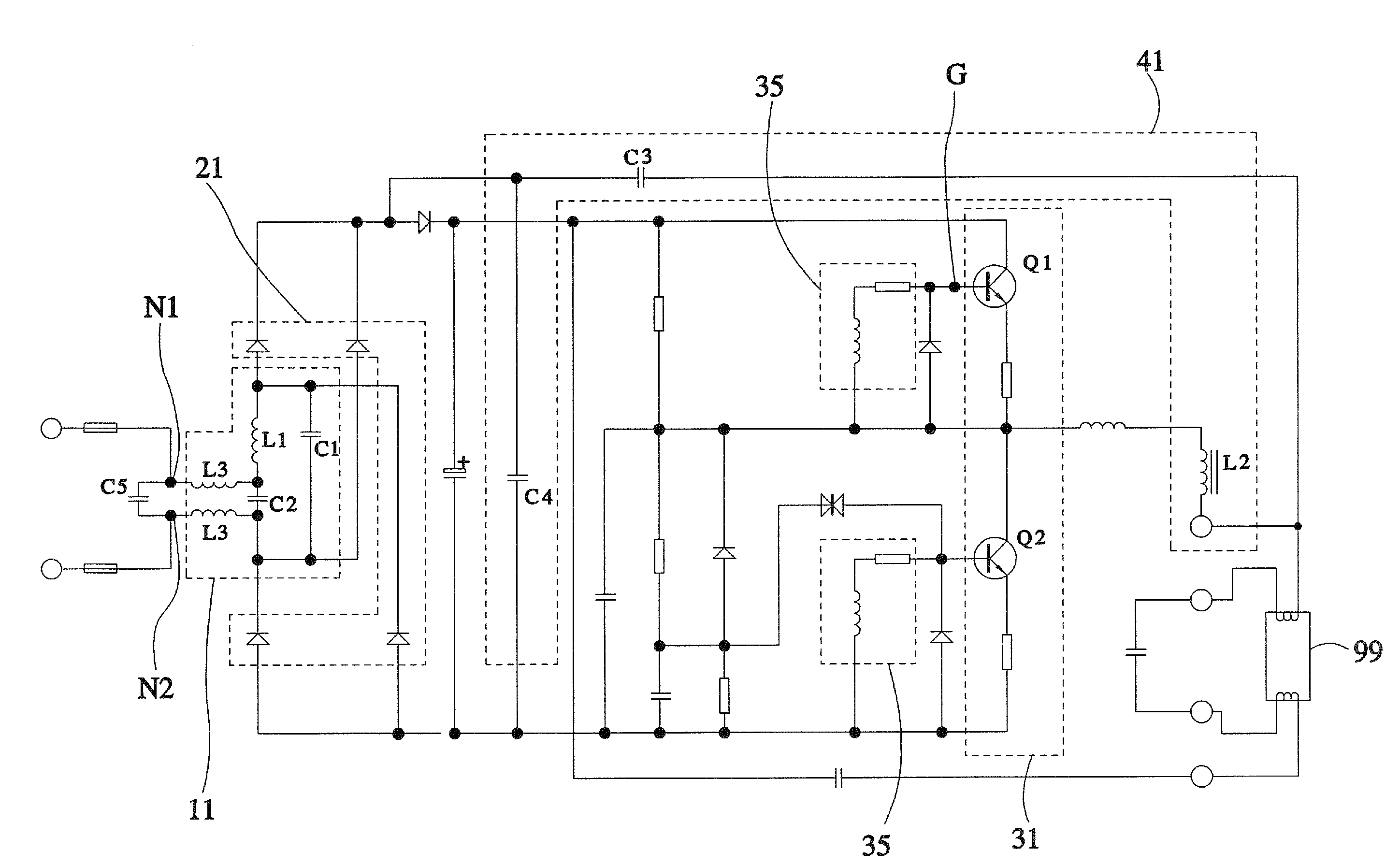
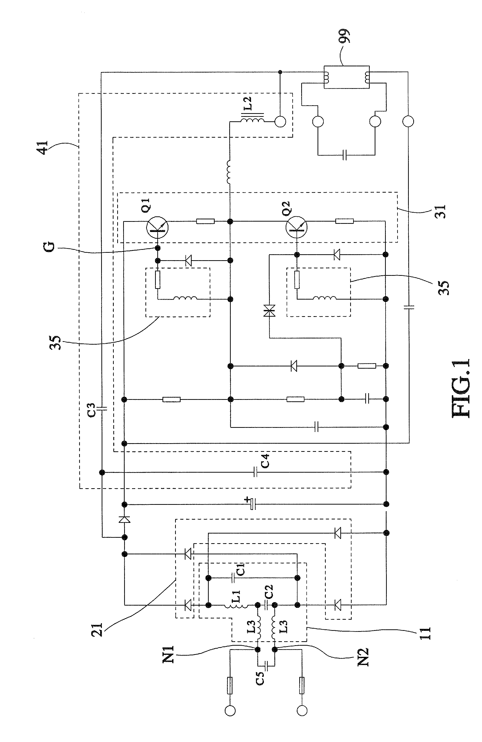
[0012]Referring to FIG. 1, an electric discharge light-regulation matching circuit 10 is adapted for use with a standard light regulator 51 to regulate the light intensity of an electric discharge lamp. The electric discharge light regulation matching circuit 10 is comprised of a resonance unit 11, a converter unit 21, a half-bridge output unit 31, and a voltage feedback unit 41.

[0013]The resonance unit 11 comprises a first capacitor C1 and a second capacitor C2 connected in series, and a first inductor L1 connected in parallel to the series of the first capacitor C1 and the second capacitor C2. The resonance unit 11 further comprises 2 third inductors L3. These 2 third inductors L3 each have one end respectively connected to the two opposite ends of the second capacitor C2, and the other end respectively connected to the two opposite ends of a fifth capacitor C5. The fifth capacitor C5 has its two opposite ends (terminals) N1, N2 for power input.

[0014]The converter unit 21 is conne...


PUM


Abstract

An inexpensive electric discharge light-regulation matching circuit for use with a standard light regulator to regulate the light of an electric discharge without causing flickering is disclosed to include a resonance unit, which comprises a first capacitor and a second capacitor connected in series and a first inductance connected in parallel to the first capacitor and second capacitor, a converter circuit connected to the resonance unit for converting an alternating current into a direct current, a half-bridge output unit, which comprises two electrically controlled switches connected in series to the converter unit with the respective control end respectively connected to a respective oscillation unit, and a voltage feedback unit, which is connected to the half-bridge output unit and the converter unit and comprises a second inductor, a third capacitor and a fourth capacitor that are connected in series. Further, the resonance frequency of the resonance unit is about a predetermined multiple of the working frequency of the half-bridge output unit.

Description

BACKGROUND OF THE INVENTION[0001]1. Field of the Invention[0002]The present invention relates to light regulation of an electric discharge lamp and more particularly, to an inexpensive electric discharge light-regulation matching circuit for use with a standard commercial light regulator to regulate the light of an electric discharge without causing flickering.[0003]2. Description of the Related Art[0004]A conventional commercial light regulation type electronic ballast for light-regulatable electric discharge lamp or fluorescent lamp tube generally utilizes a frequency modulation IC chip for light regulation control. However, a frequency modulation IC chip for this purpose is expensive. Therefore, an electronic ballast of this design is expensive, lowering its market acceptability.[0005]Further, there are people propose to use a non-frequency modulation type IC chip with a light regulator for regulating the light of an electric discharge. However, this kind of non-frequency modulat...

Claims


Application Information

Patent Timeline
Patent Type & Authority Applications(United States)
IPC IPC(8): H05B41/16
CPCH05B41/2825H05B41/3924H05B41/298
Inventor YEH, CHAO-CHIN
Owner CHUAN SHIH INDAL
Why Eureka
Try Eureka