Method for mounting electroacoustic component on PCB and electroacoustic component structure

a technology of electroacoustic components and mounting methods, which is applied in the direction of microphone structural associations, printed circuit non-printed electric components associations, electrical transducers, etc., can solve the problems of increasing the cost of producing electroacoustic components, and achieve the effect of reducing the effect of high temperature baking

Active Publication Date: 2021-04-29
ARIOSE ELECTRONICS
View PDF0 Cites 0 Cited by
  • Summary
  • Abstract
  • Description
  • Claims
  • Application Information

AI Technical Summary

Benefits of technology

[0006]An object of the present invention is to minimize the effects upon high temperature baking of the reflow oven on the housing of th...

Problems solved by technology

Faced with this problem, today's operators can only utilize materials that can withstand high temperature of the above reflow oven to make for...

Method used


Image

  • Method for mounting electroacoustic component on PCB and electroacoustic component structure
  • Method for mounting electroacoustic component on PCB and electroacoustic component structure
  • Method for mounting electroacoustic component on PCB and electroacoustic component structure

Examples


Embodiment Construction

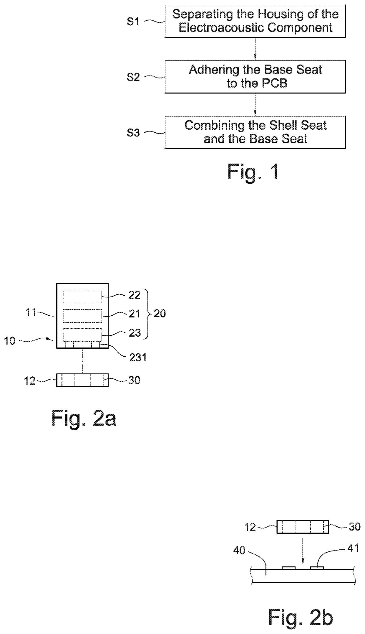
[0030]First, referring to FIG. 1, a method for mounting an electroacoustic component on a PCB according to the present invention comprises the following steps S1 to S3 being performed in sequence:

[0031]Step S1: separating the housing of the electroacoustic component;

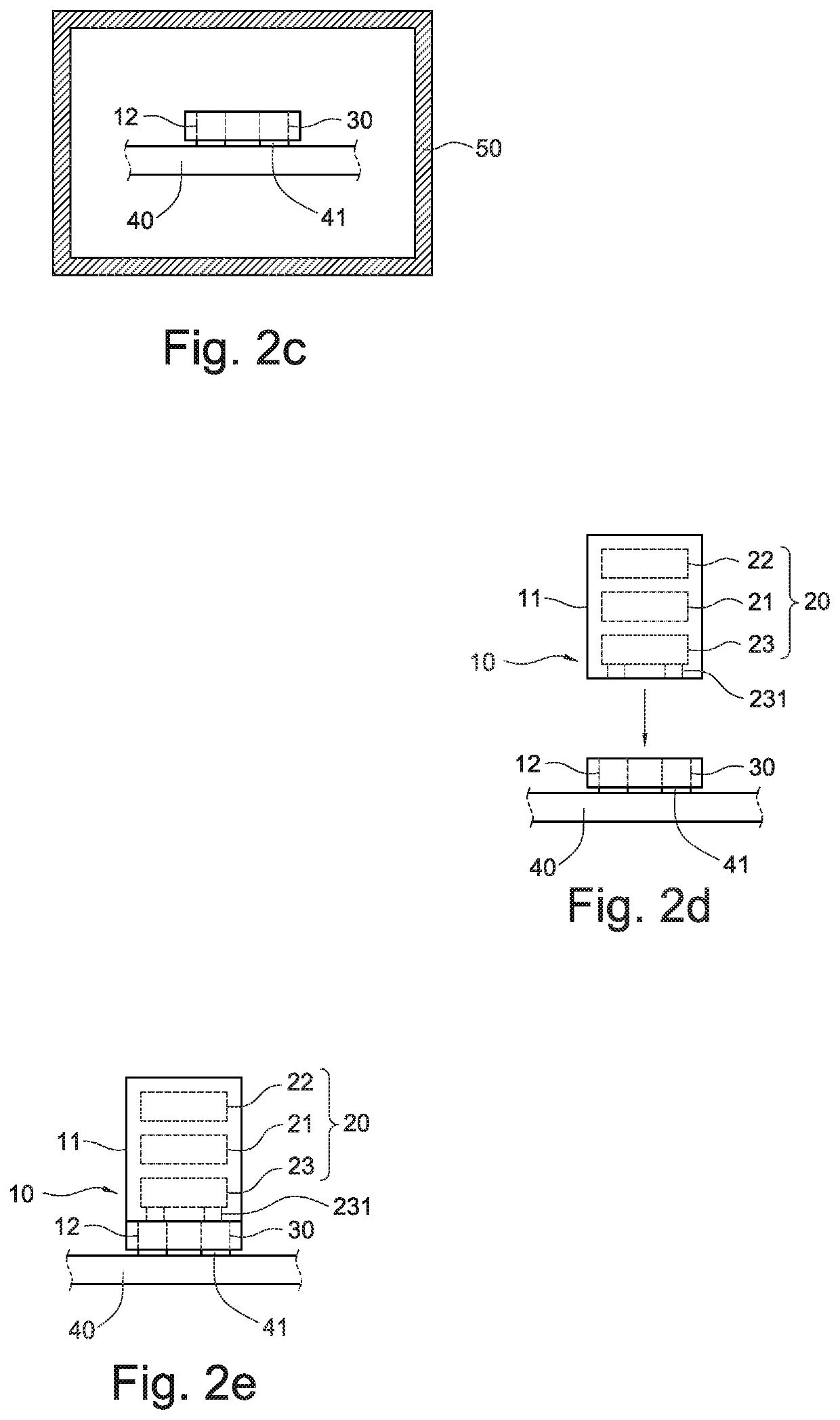
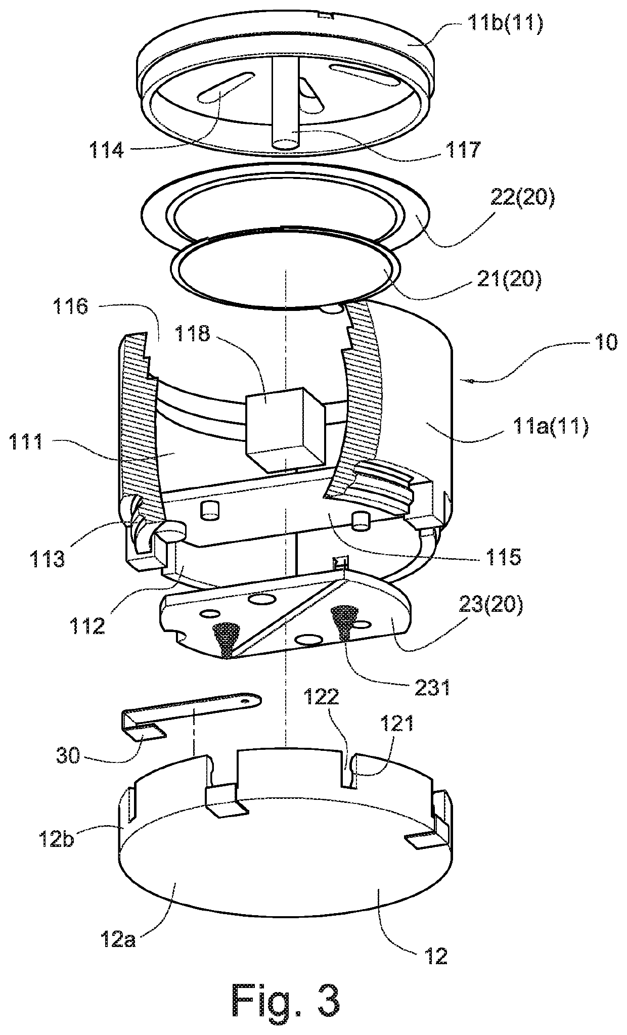
[0032]Please refer to FIG. 2a, which illustrates a pre-construction of the housing 10 of the electroacoustic component by means of a plastic injection molding technique, which can be independently integrated and then combined and integrated into a shell seat 11 and a base seat 12. The shell seat 11 is pre-installed with a plurality of sound producing components 20 having electrical characteristics susceptible to high temperature, the plurality of sound producing components 20 including at least one circuit board 23, and the base seat 12 is pre-mounted to comprise at least two conducting terminals 30. The base seat 12 is made of a heat-resistant plastic, and the shell seat 11 and the sound producing component 20 are exclu...


PUM


Abstract

This invention provides a method for mounting an electroacoustic component on a PCB and an electroacoustic component structure, so as to improve the problem that the traditional electroacoustic component affects the electrical characteristics due to the high temperature baking action in a reflow oven. The method comprises a step of separating and constructing a housing of the electroacoustic component. The housing comprises a shell seat and a base seat, the shell seat is provided with a plurality of sound producing components, and the base seat is provided with at least two conducting terminals for adhering the base seat to the PCB. The conducting terminals on the base seat and the at least two contacts on the PCB are adhered to each other and electrically connected in the reflow oven, and then the shell seat and the base seat are combined to make the shell seat and the base seat with the PCB combined outside the reflow oven into a single body to form an electroacoustic component that is mounted on the PCB.

Description

BACKGROUND OF THE INVENTION1. Field of the Invention[0001]The present invention relates to the structure and mounting technology of an electroacoustic component, and more particularly to a method and electroacoustic component structure suitable for mounting an electroacoustic component on a PCB.2. Description of Related Art[0002]Generally speaking, an electroacoustic component includes a piezoelectric buzzer, a magnetic buzzer, a dynamic speaker, and the like. Among them, the piezoelectric buzzer uses the piezoelectric effect of the piezoelectric ceramic to drive the vibration of the diaphragm to generate sound, and the magnetic buzzer uses the electromagnetic to energize and de-energize the metal diaphragm to generate vibration and then sound. However, the dynamic speaker uses the magnetic field effect generated by the coil energization to drive the diaphragm to vibrate and sound. Therefore, the electroacoustic components are generally assembled on the PCB and sounded by the drivin...

Claims


Application Information

Patent Timeline
IPC IPC(8): H05K1/18H05K3/30
CPCH05K1/181H05K2201/10083H05K3/301H04R1/04H04R1/025H04R31/00H04R2499/11H04R1/06H05K2201/1059H05K2201/10962H05K3/3442H05K3/32
Inventor BERGGREN, MAGNUSNORDLANDER, ANDERSLU, YAOTSUN
Owner ARIOSE ELECTRONICS
Why Eureka
Try Eureka