

Cableway installation
a cableway and installation technology, applied in the field of cableways, can solve problems such as imminent accident risk situations
- Summary
- Abstract
- Description
- Claims
- Application Information
AI Technical Summary
Benefits of technology
Problems solved by technology
Method used
Image

Examples
Embodiment Construction
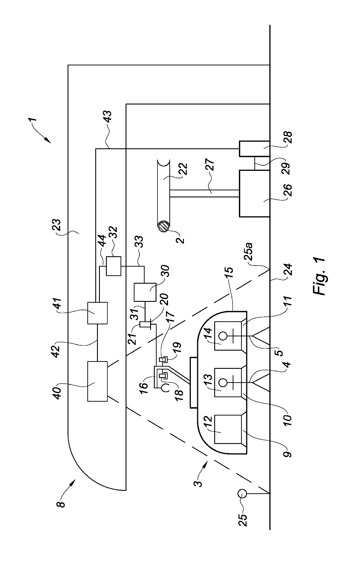
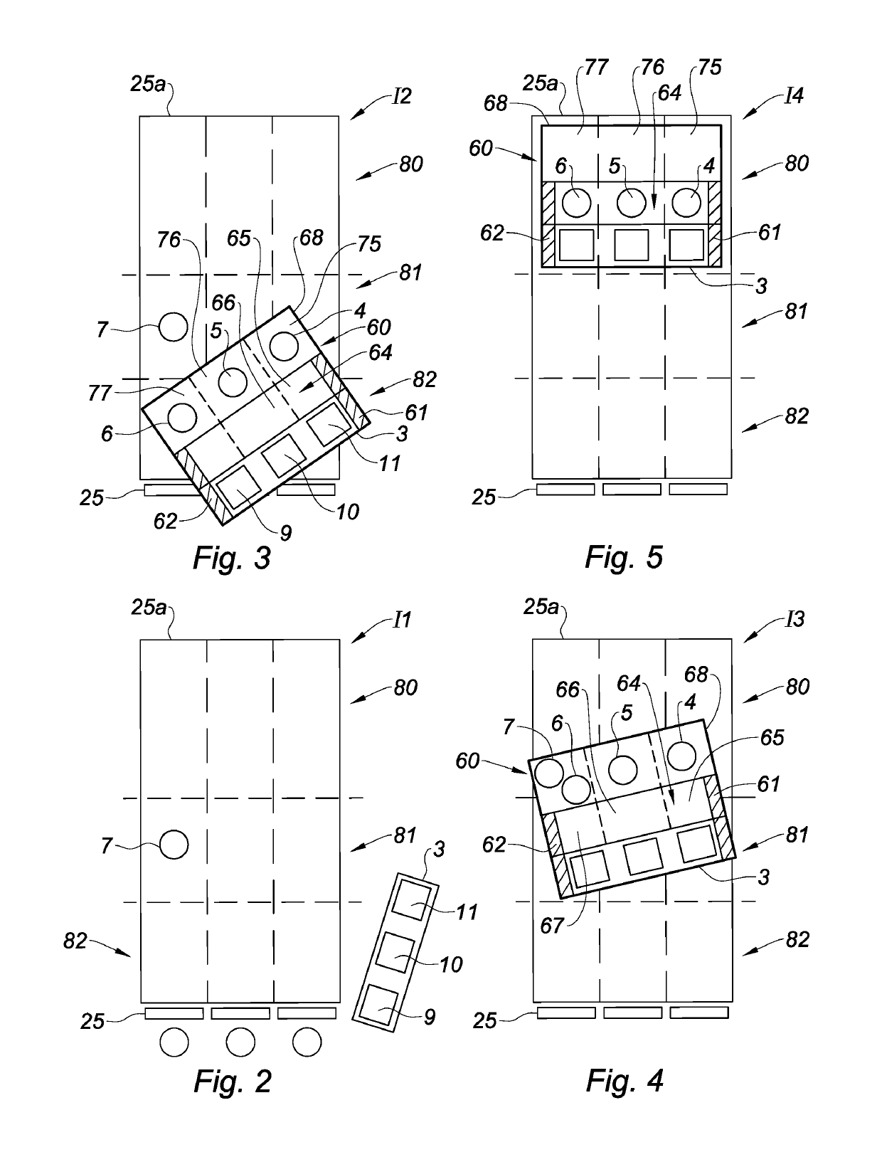
[0023]In FIG. 1, an embodiment of a cableway installation 1 has been represented. The installation 1 comprises at least one vehicle 3 designed to be hauled by the cable 2 of the installation in order to transport passengers 4 to 7. The installation 1 is preferably a chair lift, for example of monocable type. A chair lift generally comprises several vehicles 3 being chairs, and the cable 2 is an aerial hauling cable, i.e. the chairs 3 are suspended above the ground. A single chair 3 has been represented in FIGS. 1 to 5 for the sake of simplification. The cable 2 is furthermore preferably both a hauling and carrier cable. The installation 1 comprises a loading terminal 8 where the passengers 4 to 7 board the chairs 3. The chairs 3 generally comprise at least two seats 9 to 11, or even several seats, placed next to one another. Each seat 9 to 11 is designed for a passenger 4 to 7 to be seated on. In general manner, a chair 3 comprises as many backrests 12 to 14 as seats 9 to 11, a chai...
PUM
 Abstract
Description
Claims
Application Information