Ventilator with a light-emitting device

a light-emitting device and ventilator technology, applied in the direction of machines/engines, emergency power supply arrangements, and with built-in power, can solve the problems of user easily falling down or falling over something, getting hurt, and danger to elders, so as to prevent user injury, prolong the life of related elements, and save power and humidity.

Active Publication Date: 2019-09-17
SUNONWEALTH ELECTRIC MACHINE IND
View PDF13 Cites 0 Cited by
  • Summary
  • Abstract
  • Description
  • Claims
  • Application Information

AI Technical Summary

Benefits of technology

[0012]In a form shown, the ventilator with a light-emitting device further includes a power detecting circuit between the power transmitting port and the control unit, to detect a power supply status of the power transmitting port. The light-emitting device has a driving circuit and at least one emitting unit, the driving circuit electrically connects with the power detecting circuit and the at least one light emitting unit, and the at least one light emitting unit electrically connects with the power storage module. An actuating switch electrically connects the power transmitting port and the fan. Thus, the user may change the operational status of the fan by switching the actuating switch, to achieve advantages such as power saving and humidity control.
[0015]In the forms shown, a power detecting circuit electrically connects the control unit and the control switch to detect a power supply status of the power transmitting port and a connection status of the control switch. The light-emitting device has a driving circuit and at least one emitting unit, the driving circuit electrically connects with the control switch, the power detecting circuit, and the at least one light emitting unit, and the at least one light emitting unit electrically connects with the power storage module. Thus, the control unit may obtain the power supply status of the power transmitting port and the connection status of the control switch, and can change the operational status of the fan by switching the control switch, to achieve advantages such as power saving and humidity control.
[0016]In the forms shown, the power storage module has at least one battery to store electrical power. The power storage module has a discharging circuit electrically connecting the battery and the control unit to discharge the battery. The control unit electrically connects with a discharging switch, the control unit performs another judgement to determine whether the discharging switch is actuated, the control unit operates the battery to release electrical power stored therein via the discharging circuit when a result of said another judgement is positive, and the control unit stops the battery from power-discharging via the discharging circuit when the result of said another judgement is negative. A discharging period is installed in the control unit, and the control unit periodically discharges the battery via the discharging circuit based on the discharging period. The power storage module has an AC / DC converting unit electrically connecting with the power transmitting port, the battery, and the control unit. The power storage module has a step-down circuit electrically connecting with the AC / DC converting unit, the battery, and the control unit. The power storage module has a step-up circuit electrically connecting with the battery, the light-emitting device, and the control unit. Thus, the control unit may obtain the power supply status of the power transmitting port to timely use the previously stored electrical power for illumination when a power failure in the electric power grid occurs. Furthermore, by discharging the battery based on the discharging period to timely release the electric power of the battery that has not been released for a long duration of time, the lifetime of related elements can be prolonged.
[0017]In the forms shown, the control unit may be a microcontroller unit or a digital signal processor. The fan is a blower fan or an axial fan. The fan and the light-emitting device are combined with a housing, and the power storage module and the control unit are arranged inside the housing. The control unit may electrically connect with a testing switch and an indicative unit, the control unit performs another judgement to determine whether the testing switch is turned on, the control unit controls the power storage module to output electrical power stored therein to the indicative unit when the result of said another judgement is positive, and the control unit stops the power storage module from outputting the electrical power to the indicative unit when the result of said another judgement is negative. Thus, the power storage module can store electrical power in advance to energize the light-emitting device when necessary, so that the light-emitting device keeps illuminating when a power failure in the electric power grid occurs, and prevents the user from slipping down or stumbling over something and getting hurt due to the dark caused by the sudden power failure.
[0018]The present disclosed illumination device and the ventilator with a light-emitting device can use the electrical power previously stored in the power storage module to operate the light-emitting device for illumination when the electrical power supplied to the power transmitting port is fails, preventing the user from getting hurt due to slipping down caused by the dark. Additionally, the provided ventilator can further expel the humid air around the power storage module by the fan, to avoid circuit corrosion thereof and to prolong the lifetime. Therefore, the present invention can still provide illumination when electrical power fails, and can also prolong the lifetime. Furthermore, the provided illumination device and ventilator are also helpful in saving medical sources since it can prevent the user from slipping down or stumbling over something and getting hurt due to the dark caused by a sudden power failure.

Problems solved by technology

However, when a user tends to leave the dark bathroom or restroom urgently due to a sudden power failure in the electric power grid, the user may easily slip down or stumble over something and get hurt, which is especially dangerous to elders.

Method used


Image

  • Ventilator with a light-emitting device
  • Ventilator with a light-emitting device
  • Ventilator with a light-emitting device

Examples


first embodiment

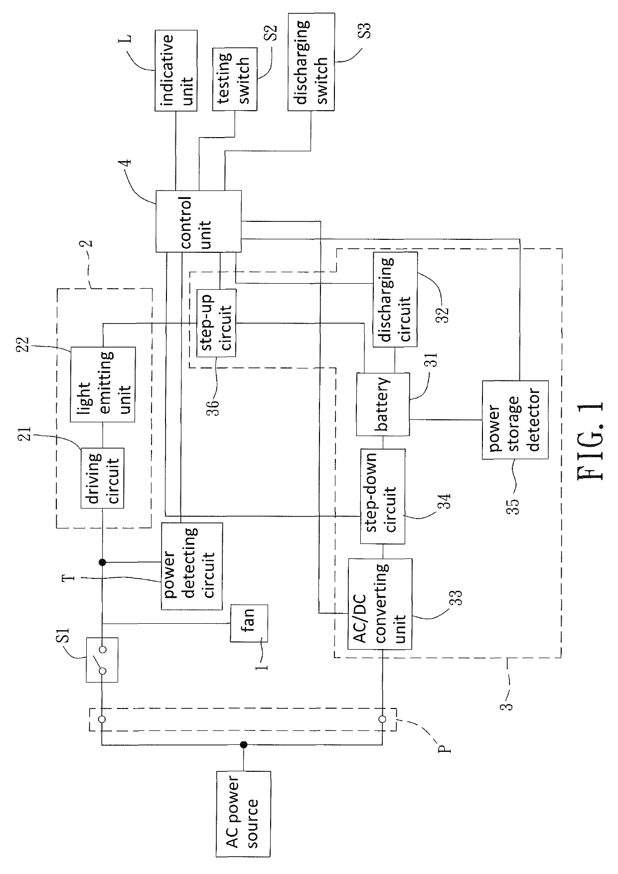
[0028]Please refer to FIG. 1 now, which shows a circuit diagram of a ventilator with a light-emitting device of the present invention, and said circuit diagram is adapted to work in an uninterruptible illumination mode. In this embodiment, the ventilator with a light-emitting device may include a fan 1, a light-emitting device 2, a power storage module 3, and a control unit 4. The fan 1 may connect to a power transmitting port P, so that the fan 1 can be rotated and generate an airflow when the power transmitting port P electrically connects with an external power source. The light-emitting device 2 is adapted to transfer the received electrical power into illumination, and it is preferable that the light-emitting device 2 directly connects with the power transmitting port P in this uninterruptible illumination mode. The power storage module 3 electrically connects with the light-emitting device 2 and the power transmitting port P for storing electrical power received from the power...
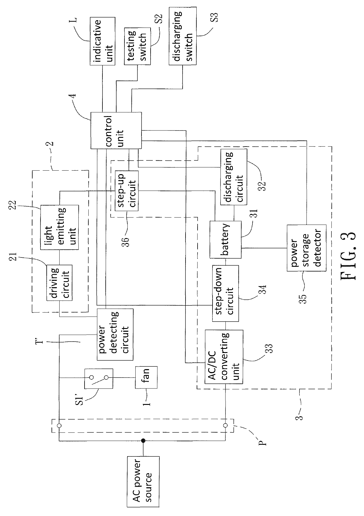
second embodiment

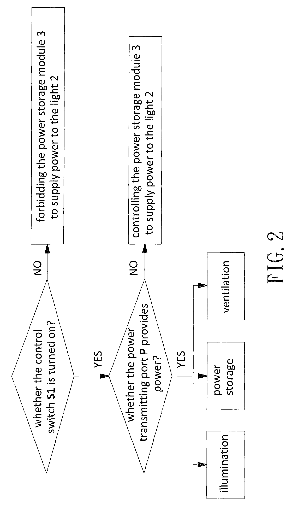
[0036]Particularly, the control unit 4 of this second embodiment is able to determine whether the power transmitting port P normally provides electrical power. If the result of the determination is positive, the control unit 4 may control the power storage module 3 to store electrical power sourced from the power transmitting port P. For example, the control unit 4 can output an enable signal to the step-down circuit 34 for providing electrical power with a voltage level acceptable to the battery 31, to recharge the battery 31. Under this situation, the light-emitting device 2 does not emit illumination, and the fan 1 can operate according to the connection status of the actuating switch S1′. Alternatively, if the result of the determination is negative, the control unit 4 may control the power storage module 3 to output the stored electrical power to the light-emitting device 2. For example, the control unit 4 may output another enable signal to the step-up circuit 36, so that the ...


PUM


Abstract

An illumination device and a ventilator include: a fan electrically connecting to a power transmitting port to be rotated for generating an airflow; a light-emitting device for transferring electrical power into illumination; a power storage module electrically connecting with the light-emitting device and the power transmitting port; and a control unit electrically connecting with the power storage module and the power transmitting port. The control unit determines whether the power transmitting port provides electrical power, the control unit controls the power storage module to store electrical power sourced from the power transmitting port when a result of the determination is positive, and the control unit controls the power storage module to output electrical power stored therein to the light-emitting device when the result of the determination is negative.

Description

CROSS REFERENCE TO RELATED APPLICATIONS[0001]The application claims the benefit of Taiwan application serial No. 105107799, filed on Mar. 14, 2016 and Taiwan application serial No. 105123103, filed on Jul. 21, 2016, and the entire contents of which are incorporated herein by reference.BACKGROUND OF THE INVENTION[0002]1. Field of the Invention[0003]The present invention generally relates to an illumination device as well as a ventilator and, more particularly, to an illumination device or a ventilator able to provide illuminance when power failure occurs.[0004]2. Description of the Related Art[0005]In a bathroom or a restroom, in addition to the light-emitting device for illumination, a ventilator for enhanced ventilation is also commonly used, to expel humidity or smells in the air from the room. Therefore, it is the trend developing a combination of a ventilator and a light-emitting device for the above described purpose. A conventional equipment resulting from this idea is disclos...

Claims


Application Information

Patent Timeline
Patent Type & Authority Patents(United States)
IPC IPC(8): F21S8/02F21S9/02F21V33/00F24F7/06H02J7/00H02J9/06H05B33/08F24F11/89F24F7/00F21Y115/10H05B44/00
CPCF24F7/065H02J9/06H02J9/065H02J7/0068H05B33/0842H05B33/0809F21S9/022F21V33/0096F24F11/89F21S8/026H05B33/0803F21Y2115/10F24F2007/001F24F2221/02F04D25/08F21S9/02H02J9/061H05B47/17H05B45/375H05B45/30H05B45/38
Inventor HORNG, ALEXTENG, TSUN-CHUNG
Owner SUNONWEALTH ELECTRIC MACHINE IND
Why Eureka
Try Eureka