
Headphones and speaker unit

a headphone and speaker technology, applied in the field of speakers, can solve the problems of reducing the strength affecting the reproduction of sound quality, and reducing so as to reduce the vibration of the edge portion, reduce the vibration of the damping member, and improve the sound reproduction

Inactive Publication Date: 2019-09-17
ONKYO HOME ENTERTAINMENT CORP
View PDF11 Cites 2 Cited by
  • Summary
  • Abstract
  • Description
  • Claims
  • Application Information

AI Technical Summary

Benefits of technology

[0009]The headphones of the present invention include a speaker unit having a diaphragm and a frame supporting an outer peripheral portion of the diaphragm, a housing configured to house the speaker unit, and a damping member made of a material member exhibiting air permeability and attached to cover an opening of the frame through which a sound wave emitted from the diaphragm passes and / or an opening of the housing. The damping member has one or more air holes formed by removal of the material forming the damping member. A secondary damping member is attached to an annular edge portion defining each air hole, thereby reducing vibration of the edge portion.
[0011]Moreover, the headphones of the present invention include a speaker unit having a diaphragm and a frame supporting an outer peripheral portion of the diaphragm, a housing configured to house the speaker unit, and a damping member made of a material exhibiting air permeability and attached to cover an opening of the frame through which a sound wave emitted from the diaphragm passes and / or an opening of the housing. The damping member has one or more air holes formed by removal of the material forming the damping member. The frame and / or the housing has an air hole edge fixing portion extending inward of the opening from a base defining the opening to fix an annular edge portion defining each air hole of the damping member, thereby reducing vibration of the edge portion.
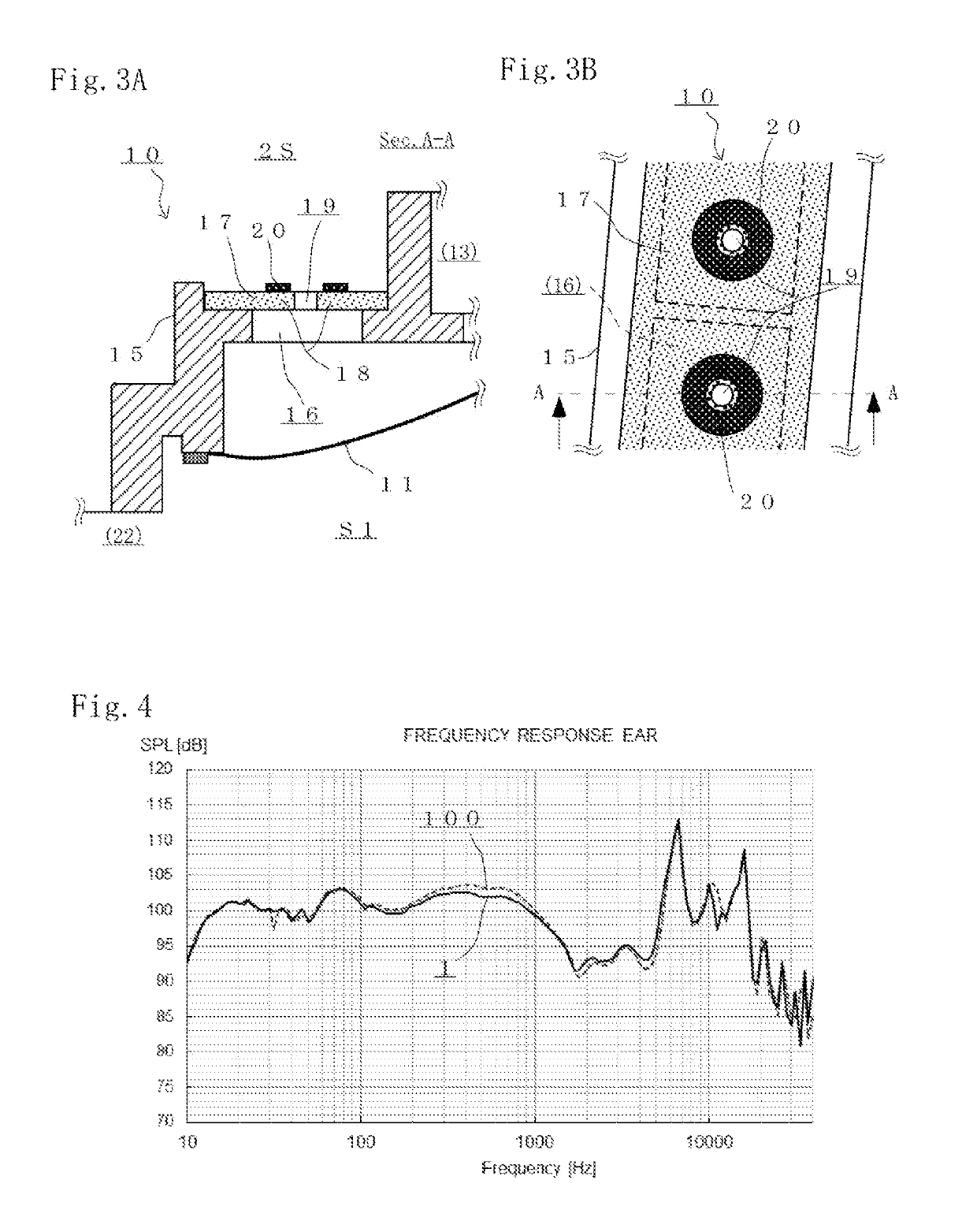
[0016]In one preferred embodiment of the present invention, the secondary damping member is attached to the annular edge portion defining each air hole of the damping member, thereby reducing vibration of the edge portion. Thus, even when the air holes are provided at the damping member, the strength of the damping member can be held by the secondary damping member, and vibration of the periphery of each air hole, which has a great air flow rate, of the damping member can be reduced. The material of the secondary damping member is not limited as long as the secondary damping member reduces vibration of the edge portion. Preferably, any of the paper member, the non-woven fabric member, the woven fabric member, and the porous member formed in the annular shape according to the shape of the edge portion defining each air hole can be employed. As a result, the headphones of the present invention have proper acoustic properties, and exhibit excellent reproduced sound quality.
[0017]In another preferred embodiment of the present invention, the frame and / or the housing has the air hole edge fixing portion extending inward of the opening from the base defining the opening to fix the annular edge portion defining each air hole of the damping member. The air hole edge fixing portion has, on the inside thereof, the hole communicating with each air hole of the damping member, thereby reducing vibration of the edge portion of each air hole of the damping member. In a case where the frame and / or the housing is made of resin or metal, the air hole edge fixing portion may be formed in the annular shape according to the shape of the edge portion defining each air hole of the damping member. Thus, even when the air holes are provided at the damping member, the strength of the damping member can be held by the air hole edge fixing portion, and vibration of the periphery of each air hole, which has a great air flow rate, of the damping member can be reduced. As a result, the headphones of the present invention have proper acoustic properties, and exhibit excellent reproduced sound quality.
[0018]Note that in the speaker unit forming the above-described headphones of the present invention, the damping member is attached to cover the opening of the frame through which the sound wave emitted from the diaphragm passes. As in any of the above-described cases, the secondary damping member configured to reduce vibration of the edge portion of each air hole of the damping member may be provided, or the air hole edge fixing portion may be provided at the frame. Thus, the headphones exhibiting excellent reproduced sound quality can be produced.
[0019]According to the headphones and the speaker unit of the present invention, headphones and a speaker unit having proper acoustic properties and exhibiting excellent reproduced sound quality can be provided even in a case where an air hole is provided at a damping member.

Problems solved by technology

However, when the air hole is provided at the damping member, there might be the following problems: the strength of the damping member is decreased; and the periphery of the air hole with a great air flow rate easily vibrates, and for this reason, such vibration of the damping member needs to be reduced.
In design of the headphones attached to the user's ears, an unnecessary sound wave emitted due to vibration of other members of the headphones than a diaphragm of the speaker unit provides a great adverse effect to the reproduced sound quality.

Method used


Image

  • Headphones and speaker unit
  • Headphones and speaker unit
  • Headphones and speaker unit

Examples


first embodiment

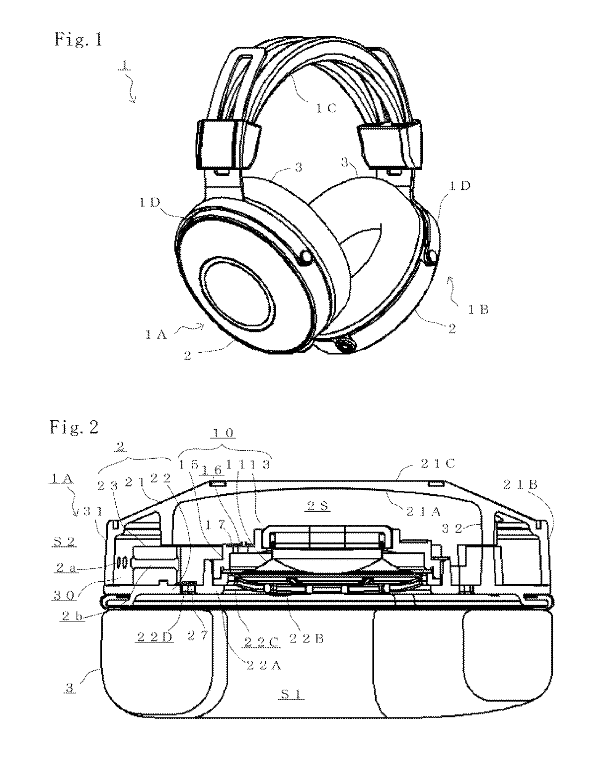
[0027]FIG. 1 is a view for describing headphones 1 according to the preferred embodiment of the present invention. Specifically, FIG. 1 is a perspective view of an outer appearance of the headphones 1. Note that the form of the headphones 1 is not limited to that in the case of the present embodiment. Other configurations of the headphones 1 not necessary for description of the present invention will not be shown in the figures and described.

[0028]The headphones 1 of the present embodiment include right and left headphone units 1A, 1B and a headband 1C coupling these headphone units 1A, 1B. Each of the headphone units 1A, 1B includes a housing 2 configured to house a speaker unit and an ear contact portion 3. The headband 1C is connected to each of coupling portions of hangers 1D, and the hangers 1D are each coupled to the housings 2.

[0029]The headphones 1 are provided with multiple holes 2a (illustrated in FIG. 2) at a side portion of each housing 2, and an internal space of the ho...

second embodiment

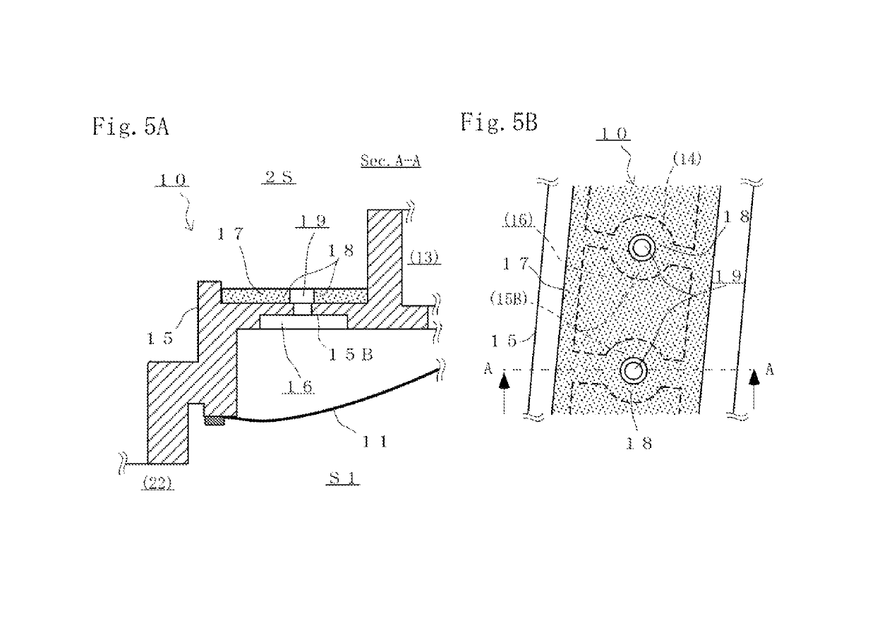
[0054]FIGS. 5A and 5B are views for describing the structure of another speaker unit 10A used for a headphone unit 1A (or 1B). The speaker unit 10A of the present embodiment is different from the speaker unit 10 of the above-described embodiment in part of the configuration of a frame 15A and a point that no secondary damping member 20 is provided, and other configurations of the speaker unit 10A are common to those of the speaker unit 10. Thus, the same reference numerals are used to represent common configurations, and description thereof will not be repeated.

[0055]Specifically, as in FIGS. 3A and 3B, FIG. 5B is an enlarged partial view of an outer peripheral side of the frame 15A of the speaker unit 10A from a back side (i.e., an internal space 2S side), and FIG. 5A is an enlarged partial sectional view of the speaker unit 10A along an A-A line of FIG. 5B.

[0056]In the frame 15A of the speaker unit 10A, an air hole edge fixing portion 15B for fixing an annular edge portion 18 defi...


PUM


Abstract

There are provided headphones and a speaker unit having proper acoustic properties and exhibiting excellent reproduced sound quality even in the case of providing air holes at a damping member. The headphones include a speaker unit having a diaphragm and a frame supporting an outer peripheral portion of the diaphragm, a housing configured to house the speaker unit, and a damping member made of a material exhibiting air permeability and attached to cover an opening of the frame through which a sound wave emitted from the diaphragm passes and / or an opening of the housing. The damping member has one or more air holes formed by removal of the material forming the damping member. A secondary damping member is attached to an annular edge portion defining each air hole, thereby reducing vibration of the edge portion.

Description

BACKGROUND OF THE INVENTION1. Field of the Invention[0001]The present invention relates to a speaker unit of headphones and earphones attached to user's ears to reproduce audio, and specifically relates to headphones and a speaker unit having a damping member through which a sound wave emitted from a diaphragm passes.2. Description of the Related Art[0002]Each of headphones includes a speaker unit, a housing surrounding a backside of the speaker unit, and an ear contact portion provided on a front side of the speaker unit. The headphones include headphones having a pair of right and left housings coupled together through a headband, earphones configured such that housings are directly supported in user's ears, and a so-called headset including a microphone device at a housing.[0003]Among the headphones of this type, there are headphones configured such that a damping member which exhibits air permeability and through which a sound wave emitted from a diaphragm passes is provided at ...

Claims


Application Information

Patent Timeline
Patent Type & Authority Patents(United States)
IPC IPC(8): H04R1/10H04R1/28H04R7/16H04R5/033
CPCH04R1/10H04R1/2873H04R1/2876H04R1/2834H04R5/033H04R7/16H04R1/1008H04R1/2849H04R1/2823H04R2420/07
Inventor MURAMOTO, SHUNTAMADERA, AKIRAOUCHI, TAKASHI
Owner ONKYO HOME ENTERTAINMENT CORP
Learn More