Personalization of powered surgical devices

a surgical device and personalization technology, applied in the field of electromechanical surgical instruments, can solve the problem that clinicians no longer have the ability to tailor the firing speed of these instruments

Active Publication Date: 2019-09-24
TYCO HEALTHCARE GRP LP
View PDF477 Cites 444 Cited by
  • Summary
  • Abstract
  • Description
  • Claims
  • Application Information

AI Technical Summary

Problems solved by technology

However, with introduction of powered surgical stapling devices, which operate by actuation of switches and / or buttons, clinicians no longer have the ability to tailor the firing speed of these instruments.

Method used


Image

  • Personalization of powered surgical devices
  • Personalization of powered surgical devices

Examples


Embodiment Construction

[0028]As used herein, the terms parallel and perpendicular are understood to include relative configurations that are substantially parallel and substantially perpendicular up to about + or −10 degrees from true parallel and true perpendicular.

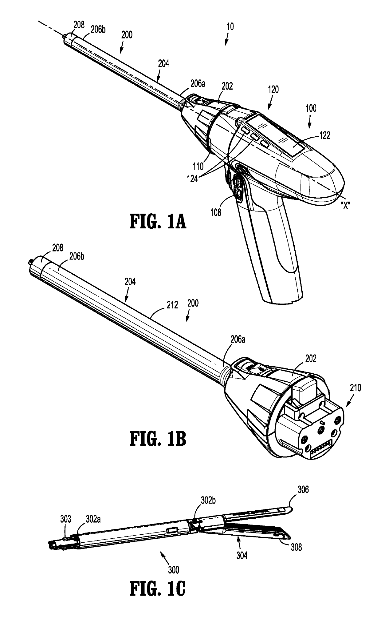
[0029]Embodiments of the presently disclosed surgical instruments including handle assemblies, adapter assemblies, and surgical loading units thereof, are described in detail with reference to the drawings, in which like reference numerals designate identical or corresponding elements in each of the several views. As used herein, the term “distal” refers to that portion of the surgical instrument, adapter assembly, handle assembly, loading unit, or component thereof, farther from the user, while the term “proximal” refers to that portion of the surgical instrument, adapter assembly, handle assembly, loading unit or component thereof, closer to the user.

[0030]The present disclosure provides a surgical instrument that includes a handle assembly,...


PUM


Abstract

A surgical instrument includes a motor configured to actuate end effector; a communication interface configured to couple to a configuration device; and a controller coupled to the motor and the communication interface, the controller includes a memory configured to store an operational parameter for operating the motor, the controller configured to modify the operational parameter based on configuration data received from the configuration device.

Description

CROSS-REFERENCE TO RELATED APPLICATIONS[0001]This application claims the benefit of and priority to U.S. Provisional Patent Application No. 62 / 271,044 filed Dec. 22, 2015, the entire disclosure of which is incorporated by reference herein.BACKGROUND[0002]1. Technical Field[0003]The present disclosure relates to electromechanical surgical system and their methods of use. More specifically, the present disclosure relates to reprogrammable and / or reconfigurable electromechanical surgical instruments.[0004]2. Background of Related Art[0005]Linear clamping, cutting, and stapling surgical devices may be employed in surgical procedures to resect tissue. Conventional linear clamping, cutting, and stapling devices include a handle assembly, an adapter assembly extending from the handle assembly, and a surgical loading unit detachably coupled to the adapter assembly. The surgical loading unit includes a pair of opposing gripping jaw members, which clamp about the tissue. In this device, one o...

Claims


Application Information

Patent Timeline
Patent Type & Authority Patents(United States)
IPC IPC(8): A61B17/072A61B17/068A61B90/00A61B34/00A61B17/00
CPCA61B90/06A61B34/25A61B17/072A61B17/068A61B17/07207A61B2017/00115A61B2017/07214A61B2017/07271A61B2017/00017A61B2017/07257A61B2017/00199A61B2017/00398A61B2090/0807A61B2017/07285A61B2017/00221A61B2017/0046A61B2034/258A61B2017/00367A61B2017/00473A61B17/3209A61B2017/00982
Inventor COLLINGS, PETERVALENTINE, KELLYBLAKE, JESSICA
Owner TYCO HEALTHCARE GRP LP
Why Eureka
Try Eureka