Rolling mill and rolling method

a rolling mill and rolling method technology, applied in the direction of measuring devices, profile control devices, manufacturing tools, etc., can solve the problems of insufficient spindle strength, inability to achieve stable rolling, so as to reduce rolling load and good strip shape

Active Publication Date: 2019-09-24
PRIMETALS TECHNOLOGIES JAPAN LTD
View PDF12 Cites 2 Cited by
  • Summary
  • Abstract
  • Description
  • Claims
  • Application Information

AI Technical Summary

Benefits of technology

[0025]With the present invention, a rolling material with a good strip shape can be obtained even when the diameters of work rolls are reduced for the purpose of reducing rolling load.

Problems solved by technology

However, the reduction in diameter of work rolls causes insufficient spindle strength and thus requires switching from work-roll drive to intermediate-roll drive.
This has led to a problem in that the deflection distorts the strip shape and makes it impossible to achieve stable rolling.
This has led to a similar problem in that stable rolling cannot be achieved.

Method used


Image

  • Rolling mill and rolling method
  • Rolling mill and rolling method
  • Rolling mill and rolling method

Examples


embodiment 1

[0047]{Embodiment 1}

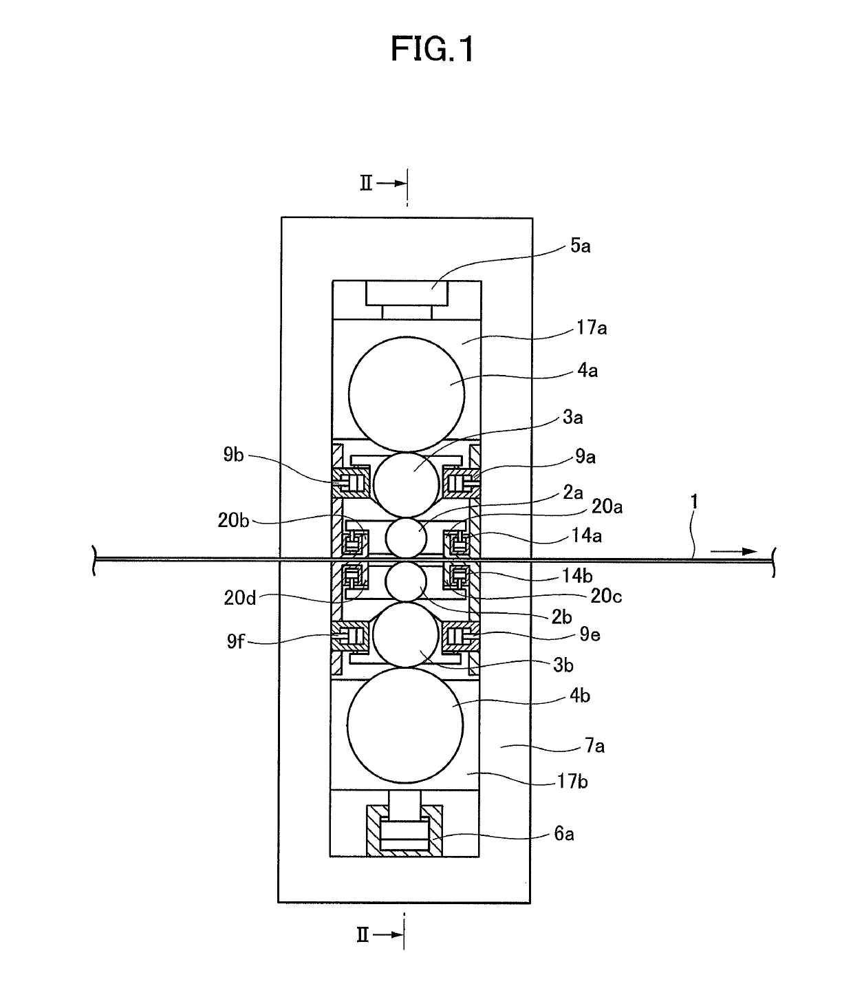
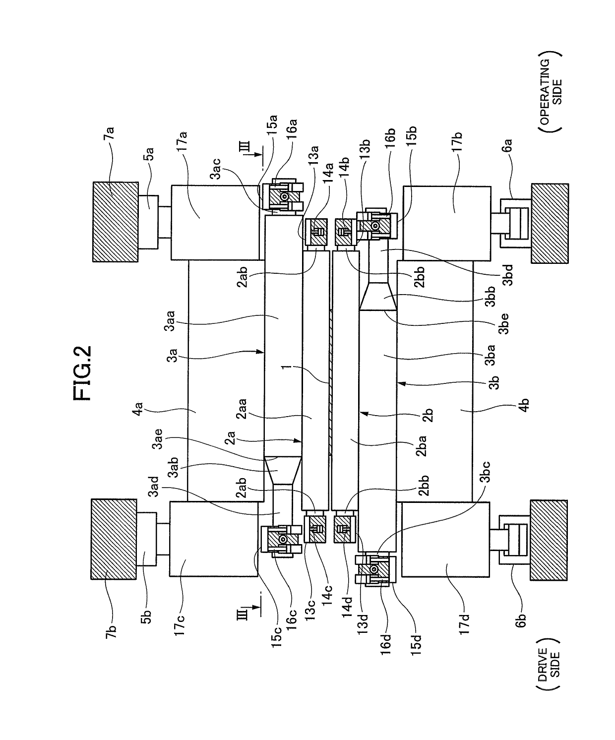
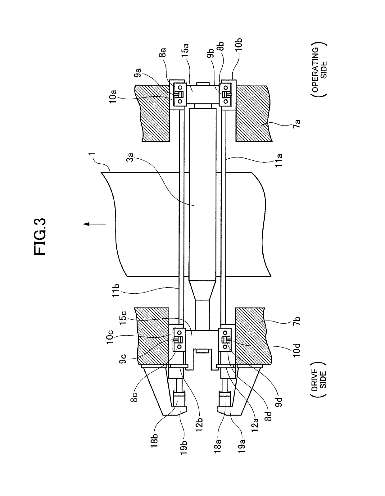
[0048]As shown in FIGS. 1 and 2, a six-high rolling mill according to the present embodiment includes left and right (drive side and operating side) housings 7a, 7b as a pair. Upper and lower work rolls 2a, 2b as a pair, upper and lower intermediate rolls 3a, 3b as a pair, and upper and lower back-up rolls 4a, 4b as a pair are rotatably supported inside the housings 7a, 7b. The work rolls 2a, 2b are in contact with and supported by the intermediate rolls 3a, 3b, respectively. The intermediate rolls 3a, 3b are in contact with and supported by the back-up rolls 4a, 4b, respectively. A rolling material 1 which is a hard material conveyed between the housings 7a, 7b are passed between the work rolls 2a, 2b and thereby rolled.

[0049]The upper back-up roll 4a is rotatably supported by bearings (not shown) and bearing chocks 17a, 17c. The bearing chocks 17a, 17c are supported by the housings 7a, 7b via pass line adjusting devices 5a, 5b. In other words, by driving the pa...

embodiment 2

[0102]{Embodiment 2}

[0103]A rolling mill and a rolling method according to a second embodiment of the present invention will be described with reference to FIG. 13.

[0104]The present embodiment has a configuration obtained by adding load cells to the first embodiment, which is shown in FIGS. 1 to 4 and described above. The other features of the configuration are mostly similar to the rolling mill shown in FIGS. 1 to 4 and described above. The same instruments will be denoted by the same reference signs, and redundant description thereof will be omitted as appropriate.

[0105]As shown in FIG. 13, the rolling mill according the present embodiment includes load cells 27a, 27b, 27c, 27d, 27e, 27f, 27g, 27h disposed between the above-mentioned shift blocks and intermediate-roll-offset changing cylinders 9a, 9b, 9c, 9d, 9e, 9f, 9g, 9h.

[0106]Note that the load cells 27b, 27d are disposed on the inlet side in the conveyance direction of a rolling material 1 relative to an upper intermediate r...

embodiment 3

[0118]{Embodiment 3}

[0119]A rolling mill and a rolling method according to a third embodiment of the present invention will be described with reference to FIG. 14.

[0120]The present embodiment has a configuration obtained by adding load cells to the first embodiment, which is shown in FIGS. 1 to 4 and described above. The other features of the configuration are mostly similar to the rolling mill shown in FIGS. 1 to 4 and described above. The same instruments will be denoted by the same reference signs, and redundant description thereof will be omitted as appropriate.

[0121]As shown in FIG. 14, the rolling mill according to the present embodiment includes load cells 28a, 28b, 28c, 28d, 28e, 28f, 28g, 28h disposed between bearing chocks for work rolls 2a, 2b and the projection blocks mentioned above.

[0122]Note that the load cells 28b, 28d are disposed on the inlet side in the conveyance direction of a rolling material 1 relative to the upper work roll 2a. The load cells 28a, 28c are dis...


PUM

PropertyMeasurementUnit
thicknessaaaaaaaaaa
thicknessaaaaaaaaaa
thicknessaaaaaaaaaa

Abstract

A rolling mill includes: work rolls configured to roll a rolling material; intermediate rolls supporting the work rolls from above and below, respectively; back-up rolls supporting the intermediate rolls from above and below, respectively; position adjusting means for adjusting the positions of the intermediate rolls relative to the work rolls and the back-up rolls in the direction of conveyance of the rolling material; detecting means for detecting horizontal forces on the work rolls; offset-amount calculating means for calculating the offset amounts of the intermediate rolls based on the horizontal forces on the work rolls detected by the detecting means; and controlling means for controlling the position adjusting means such that the positions of the intermediate rolls are offset by the offset amounts calculated by the offset-amount calculating means.

Description

TECHNICAL FIELD[0001]The present invention relates to a rolling mill and a rolling method for rolling a rolling material such as a metal strip.BACKGROUND ART[0002]In recent years, in the rolling of hard materials such as electrical steel strips, high tensile strength steel, and stainless steel, the diameters of work rolls have been reduced for the purpose of reducing rolling load. However, the reduction in diameter of work rolls causes insufficient spindle strength and thus requires switching from work-roll drive to intermediate-roll drive. Here, drive tangential forces from those intermediate rolls deflect the work rolls. This has led to a problem in that the deflection distorts the strip shape and makes it impossible to achieve stable rolling. Also even with the work-roll drive, the work rolls will be deflected if the difference in tension is large between the inlet side and the outlet side of the work rolls. This has led to a similar problem in that stable rolling cannot be achie...

Claims


Application Information

Patent Timeline
Patent Type & Authority Patents(United States)
IPC IPC(8): B21B37/58B21B13/14B21B31/32B21B27/02B21B31/20B21B38/08B21B13/02
CPCB21B37/58B21B31/20B21B13/14B21B27/021B21B38/08B21B2013/028B21B31/32B21B13/142B21B1/22B21B13/147B21B29/00B21B37/38B21B38/06
Inventor NORIKURA, TAKASHI
Owner PRIMETALS TECHNOLOGIES JAPAN LTD
Why Eureka
Try Eureka