
Tape measure structure

a tape and structure technology, applied in the field of tape measure structure, can solve the problems of inability to adjust the recovery speed of the tape body, abrasion etc., and achieve the effects of preventing the user from being injured, and reducing the damage to the tape body

Active Publication Date: 2019-10-01
TOP LONG INDAL
View PDF11 Cites 0 Cited by
  • Summary
  • Abstract
  • Description
  • Claims
  • Application Information

AI Technical Summary

Benefits of technology

[0005]The main object of the present invention is to provide a tape measure structure, capable of reducing the abrasion to a tape body and preventing users from being injured.
[0008]Therefore, a user may press the flexible control element to deform it to touch the tape body to stop it without needing to directly touch the tape body with a finger during use, thereby preventing the user from being injured and reducing the abrasion to the tape body. In addition, users may use the flexible control element to achieve the objects of direct operation and adjustment through the sense of touch. Furthermore, when the tape body is wound back, the buffering of the buffer can be used to reduce the damage to the tape body and the sound generated from collision.

Problems solved by technology

However, the fixing block is made of hard material such that it will cause abrasion to the tape body.
In addition, the fixing block is selectively fixed to the housing such that the operation has no hand feeling and is unable to adjust the recovery speed of the tape body.

Method used


Image

  • Tape measure structure
  • Tape measure structure
  • Tape measure structure

Examples


Embodiment Construction

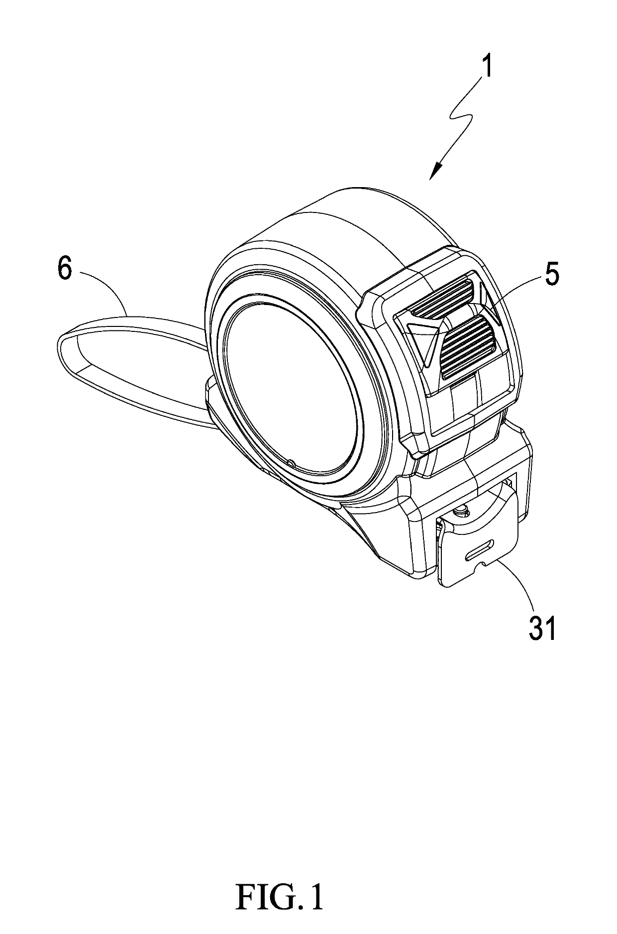
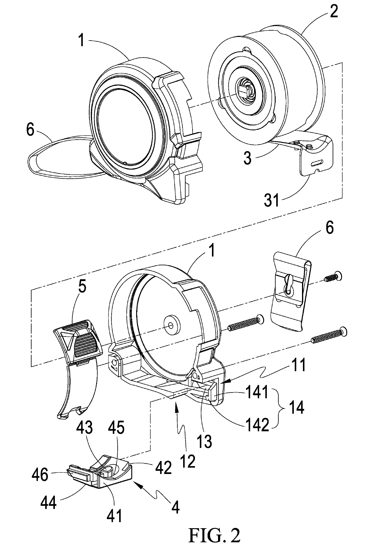
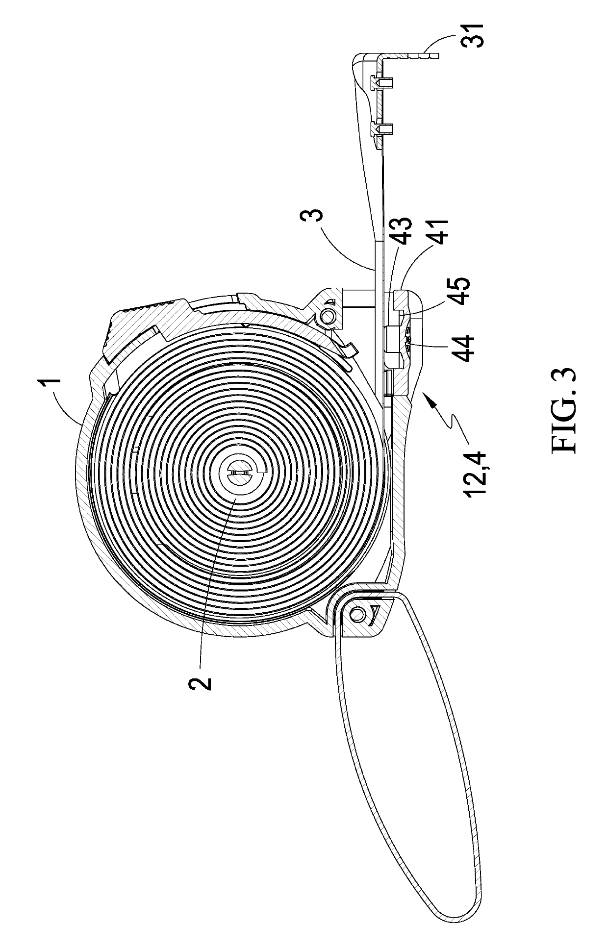
[0015]Referring to FIGS. 1 and 2, a tape measure structure of the present invention mainly includes a housing assembly 1, at least one rotation disk 2, at least one tape body 3 and at least one flexible control element 4, where the rotation disk 2 is movably configured inside the housing assembly 1, and tape body 3 is movably wound around the rotation disk 2, the end of which is selectively passed out of the housing assembly 1, where the rotation disk 2 includes at least one elastic element adapted to wind back the tape body 3.

[0016]The housing assembly 1 has at least one access opening 11 allowing the tape body 3 to be passed out thereof, at least one operation portion 12 corresponding to the tape body 3 is configured on one side of the housing assembly 1 adjacent to the access opening 11, and at least one combination portion 13 positioned at one side of the operation portion 12 is configured inside the housing assembly 1.

[0017]Furthermore, the flexible control element 4 is coupled...


PUM


Abstract

A tape measure structure is characterized in that an access opening of a housing assembly is configured with a flexible control element capable of being pressed to touch and stop a tape body movably installed inside the housing assembly, and a buffer for buffering the tape body is configured on one side of the flexible control element adjacent to the access opening. Whereby, the present invention can avoid the damage to the tape body, prevent the injury to users, and does not interfere hand feeling so as to make the operation convenient.

Description

(a) TECHNICAL FIELD OF THE INVENTION[0001]The present invention relates to a tape measure structure, and more particularly to a tape measure structure avoiding abrasion, preventing users from being damaged, and convenient for operation without interfering with hand feeling.(b) DESCRIPTION OF THE PRIOR ART[0002]Traditional tape measures include an outer housing, winder configured inside the outer housing, tape body wound around the winder and fixing block movably configured on the outer housing, where the tape body can be pulled out to carry out measurement and the fixing block can also be operated to move to be in touch with and fix the ruler body when used. However, the fixing block is made of hard material such that it will cause abrasion to the tape body. In addition, the fixing block is selectively fixed to the housing such that the operation has no hand feeling and is unable to adjust the recovery speed of the tape body.[0003]Therefore, conventional touch tape measures are avai...

Claims


Application Information

Patent Timeline
Patent Type & Authority Patents(United States)
IPC IPC(8): G01B3/10
CPCG01B3/1005G01B3/1041G01B2003/1053G01B2003/1033G01B2003/1043G01B3/1043
Inventor KUO, SHAO-FAN
Owner TOP LONG INDAL
Learn More