Control device of head mounted display, operation method and operation program thereof, and image display system

a control device and display technology, applied in the direction of mechanical pattern conversion, instruments, optical elements, etc., can solve the problems of poor usability and bad usability, and achieve the effect of improving usability and effectively preventing the error of gesture recognition

Active Publication Date: 2019-10-01
FUJIFILM CORP
View PDF9 Cites 13 Cited by
  • Summary
  • Abstract
  • Description
  • Claims
  • Application Information

AI Technical Summary

Benefits of technology

[0010]An object of the present invention is to provide a control device of a head mounted display, an operation method and a non-transitory computer readable recording medium storing an operation program thereof, and an image display system in which erroneous recognition of a gesture operation can be effectively prevented and usability can be improved.
[0019]According to the present invention, a double tap operation in which an operation of lowering at least one finger other than the thumb toward the thumb and then raising the finger is consecutively performed twice is set as a selection operation which is a gesture operation of selecting one of a plurality of options relating to a virtual object, and a slide operation of moving the hand with any of a wrist, an elbow, or a shoulder as a fulcrum is set as a change operation which is a gesture operation for performing change processing of changing a display form of a virtual object. Thus, it is possible to provide a control device of a head mounted display, an operation method and a non-transitory computer readable recording medium storing an operation program thereof, and an image display system in which erroneous recognition of a gesture operation can be effectively prevented and usability can be improved.

Problems solved by technology

Thus, usability is bad.
Accordingly, usability may be bad.

Method used


Image

  • Control device of head mounted display, operation method and operation program thereof, and image display system
  • Control device of head mounted display, operation method and operation program thereof, and image display system
  • Control device of head mounted display, operation method and operation program thereof, and image display system

Examples


first embodiment

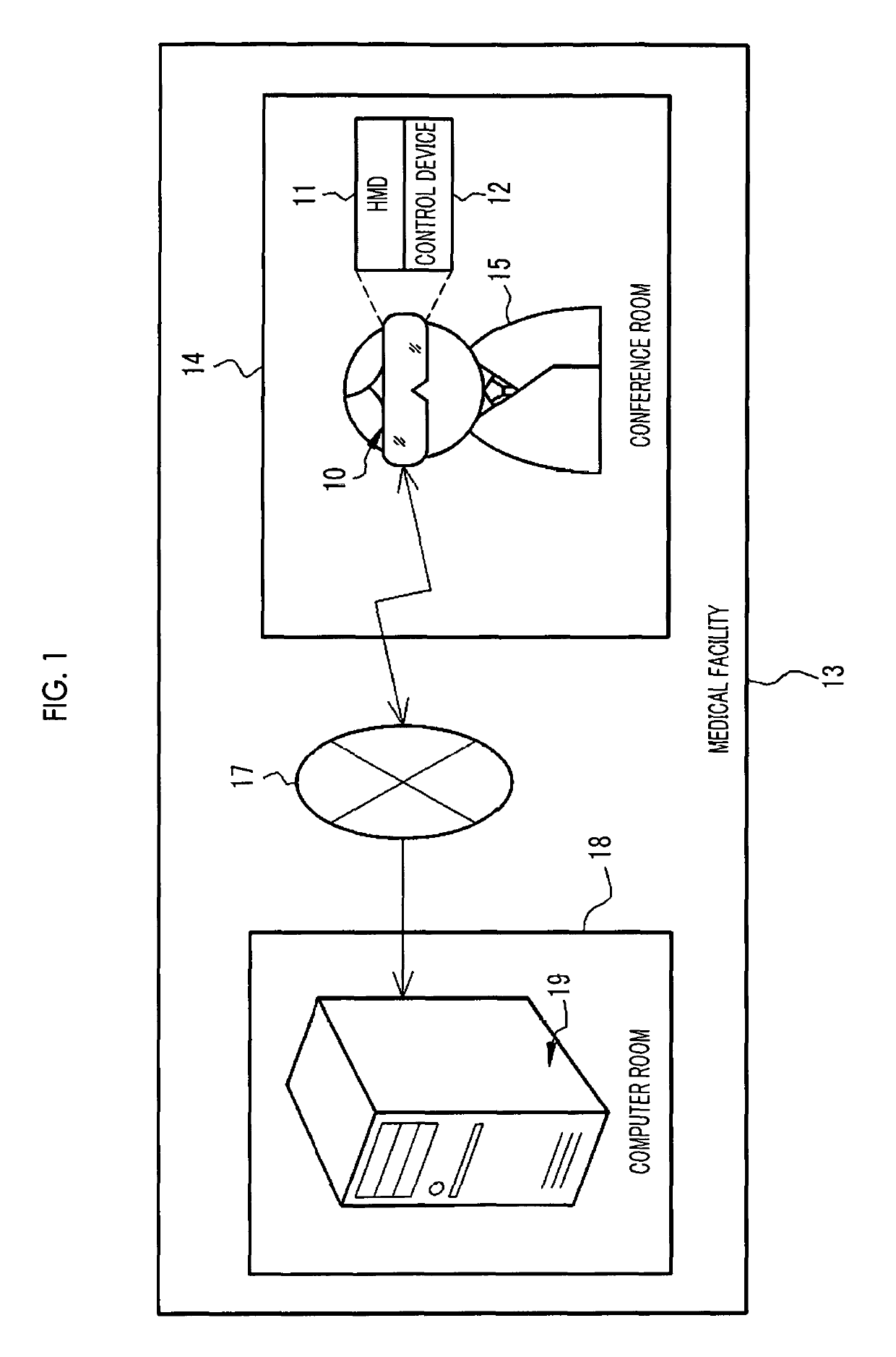
[0050]In FIG. 1, an image display system 10 is obtained by integrating an HMD 11 and a control device 12 and is used in a conference room 14 of a medical facility 13, for example. The image display system 10 is mounted on the head of a user 15. The user 15 is a medical staff such as a doctor or a nurse, who belongs to the medical facility 13. The head refers to a portion positioned upward from the neck of the human body in a standing state and includes a face and the like.

[0051]The image display system 10 is connected to an image storage server 19, for example, through a network 17 such as a local area network (LAN), so as to allow communication with each other. The image storage server 19 is installed in, for example, a computer room 18 of the medical facility 13.

[0052]The image storage server 19 stores various medical images of a patient, which have been acquired in the medical facility 13. The medical image includes a three-dimensional volume rendering image (hereinafter, 3D imag...

second embodiment

[0161]In the first embodiment, regardless of whether or not the double tap operation is provided, the adjust-mode display bar 90 and the structure list 95 are displayed as the menu bar, in the virtual space VS. However, in a second embodiment illustrated in FIG. 27, the menu bar is displayed only in a case where the double tap operation is recognized.

[0162]FIG. 27 illustrates an example of the adjust-mode display bar 90. The upper row of an arrow indicates a state where the display position among the types of change processing is selected. In this state, the display control unit 74 does not display the adjust-mode display bar 90 in the virtual space VS. In a case where the double tap operation is performed by the user 15 in order to switch the type of change processing from the display position to the display size, from the state in the upper row of the arrow, and the double tap operation is recognized by the operation recognition unit 80, the display control unit 74 displays the ad...

third embodiment

[0164]In a third embodiment illustrated in FIG. 28, the menu bar is displayed only in a case where the double tap operation is recognized, and the menu bar is displayed at the viewpoint position of the user 15.

[0165]FIG. 28 illustrates an example of the adjust-mode display bar 90, similar to the case of FIG. 27. The upper row of an arrow indicates a state where the display position among the types of change processing is selected. In a case where the double tap operation is performed by the user 15 from this state and the double tap operation is recognized by the operation recognition unit 80, the display control unit 74 displays the adjust-mode display bar 90 at the viewpoint position of the user 15, that is, the position of the cursor 41 in the virtual space VS, as in the lower row of the arrow. Then, the adjust-mode display bar 90 is erased after a predetermined time, for example, 5 seconds elapses.

[0166]As described above, since the adjust-mode display bar 90 is displayed at the...


PUM


Abstract

A selection processing unit performs selection processing of selecting one of a plurality of options relating to a 3D image, in a case where a double tap operation is recognized by an operation recognition unit, and of cyclically switching the option to be selected every time the double tap operation is recognized. A change processing unit performs change processing of changing a display form of a 3D image, which accompanies the one option selected in the selection processing unit in a case where a tap-and-hold operation is recognized by an operation recognition unit.

Description

CROSS-REFERENCE TO RELATED APPLICATIONS[0001]The present application claims priority under 35 U.S.C. § 119 to Japanese Patent Application No. 2017-078064, filed on Apr. 11, 2017. Each of the above application(s) is hereby expressly incorporated by reference, in its entirety, into the present application.BACKGROUND OF THE INVENTION1. Field of the Invention[0002]The present invention relates to a control device of a head mounted display, an operation method and a non-transitory computer readable recording medium storing an operation program of the head mounted display, and an image display system.2. Description of the Related Art[0003]A technology of displaying a virtual object using computer graphics in a head mounted display (hereinafter, HMD) mounted on the head of a user, and allowing the user to recognize the virtual object in the same manner as a real object existing in a real space is known.[0004]JP2014-071812A discloses a control device of an HMD that recognizes various gestur...

Claims


Application Information

Patent Timeline
Patent Type & Authority Patents(United States)
IPC IPC(8): G06F3/01G06F3/0481G06F3/0484G02B27/01G06T19/20G06T19/00G06F3/0486G06K9/00G06F3/0482
CPCG06T19/006G02B27/017G02B27/0172G06F3/04842G06F3/04815G06F3/017G06T19/20G06F3/011G06F3/04845G06F3/0482G06K9/00355G02B2027/014G02B2027/0187G06T2219/2016G02B2027/0141G06F3/0486G06V40/28
Inventor KAMODA, RENAOKABE, YUKI
Owner FUJIFILM CORP
Why Eureka
Try Eureka