Method of handling a plastic container having a moveable base

a technology of moving base and plastic container, which is applied in the direction of liquid handling, filling without pressure, application, etc., can solve the problems of plastic container deformation, and the known flexible base region cannot adequately compensate for vacuum forces on its own, so as to reduce the volume of the container

Inactive Publication Date: 2019-10-08
CO2 PAC
View PDF5 Cites 7 Cited by
  • Summary
  • Abstract
  • Description
  • Claims
  • Application Information

AI Technical Summary

Benefits of technology

[0016]The present invention relates to a polymeric or plastic container having an invertible pressure panel located in the container base. The pressure panel is movable from an initial, outwardly-inclined position, to an inverted, inwardly-inclined position, in order to reduce the volume of the container and accommodate for vacuum forces within the container. The entire pressure panel is set deeply into the base of the container, such that no portion of the pressure panel extends beyond the standing ring, regardless of whether the pressure panel is in the initial position or the inverted position. This configuration can allow the container to be supported by the standing ring regardless of whether the pressure panel is in the initial position or the inverted position.

Problems solved by technology

This in turn leads to deformation of the plastic container if it is not constructed rigidly enough to resist the vacuum forces.
Known flexible base regions have not been able to adequately compensate for the vacuum forces on their own (i.e., vacuum panels in the sidewall and / or or other reinforcing structures are still required).

Method used


Image

  • Method of handling a plastic container having a moveable base
  • Method of handling a plastic container having a moveable base
  • Method of handling a plastic container having a moveable base

Examples


Embodiment Construction

[0054]Embodiments of the invention are discussed in detail below. In describing embodiments, specific terminology is employed for the sake of clarity. However, the invention is not intended to be limited to the specific terminology so selected. While specific exemplary embodiments are discussed, it should be understood that this is done for illustration purposes only. A person skilled in the relevant art will recognize that other components and configurations can be used without departing from the spirit and scope of the invention. All references cited herein are incorporated by reference as if each had been individually incorporated.

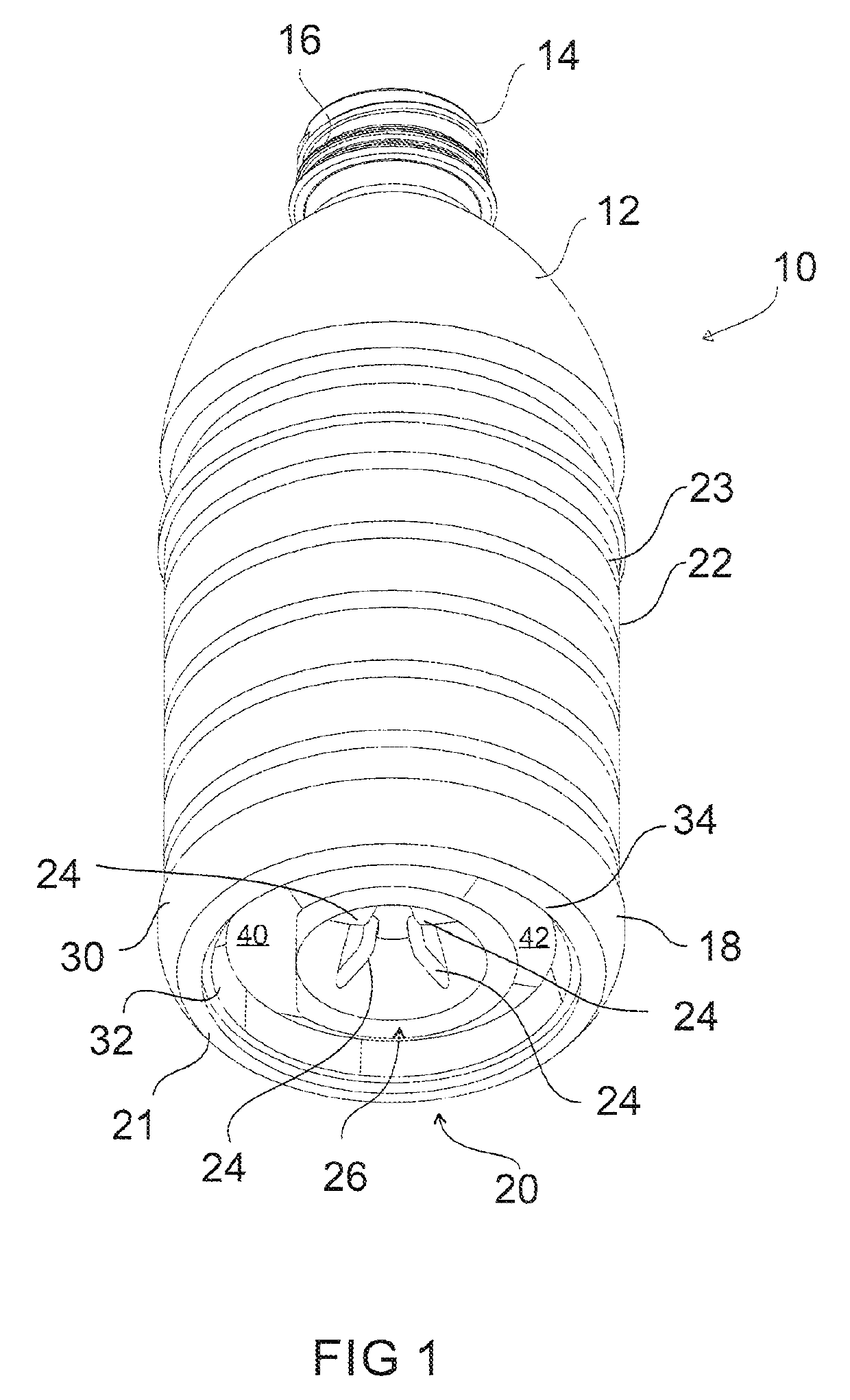
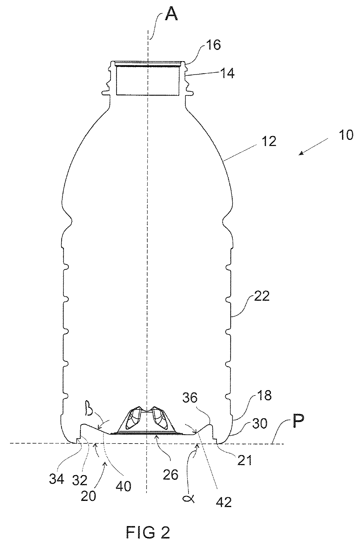
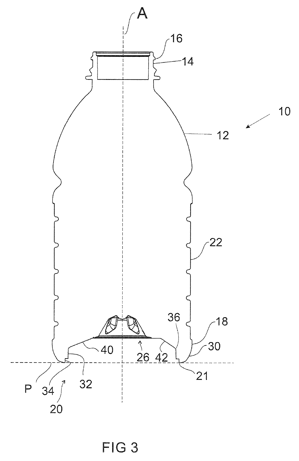
[0055]As discussed above, to accommodate vacuum forces during cooling of the liquid contents within a hot-fill container, plastic containers have typically included a series of vacuum panels located around the sidewall and / or in the base portion. The vacuum panels deform inwardly, and the base deforms upwardly, under the influence of the vacuum forces. ...


PUM

PropertyMeasurementUnit
temperatureaaaaaaaaaa
thicknessaaaaaaaaaa
thicknessaaaaaaaaaa

Abstract

A plastic container comprises an upper portion including a finish defining an opening into the container, a lower portion including a base defining a standing surface, a sidewall extending between the upper portion and the lower portion, the sidewall defining a longitudinal axis, and at least one substantially transversely-oriented pressure panel located in the lower portion. The pressure panel is movable between an outwardly-inclined position and an inwardly-inclined position to compensate for a change of pressure inside the container. The standing surface defines a standing plane, and the entire pressure panel is located between the standing plane and the upper portion of the container when the pressure panel is in the outwardly-inclined position.

Description

CROSS-REFERENCE TO RELATED APPLICATIONS[0001]The present application is a continuation of U.S. patent application Ser. No. 13 / 415,831, filed on Mar. 8, 2012 (the '831 application, and published as US2013 / 0312368), now U.S. Pat. No. 9,731,884 issued Aug. 15, 2017.[0002]The '831 application is a continuation-in-part of U.S. patent application Ser. No. 11 / 704,368, filed on Feb, 9, 2007. (the '368 application published as US 2008 / 0047964), now U.S. Pat. No. 8,584,879, issued Nov. 19, 2013. The '368 application is a continuation-in-part of U.S. patent application Ser. No. 10 / 529,198, filed on Mar. 24, 2005, with a § 371 filing date of Dec. 15, 2005, now U.S. Pat. No. 8,152,010 issued Apr. 10, 2012, which is the U.S. National Phase of International Application No, PCT / NZ2003 / 000220, filed on Sep. 30, 2003, which claims priority to New Zealand Application Ser. No. 521694, filed on Sep. 30, 2002. The '368 application is also a continuation-in-part of U.S. patent application Ser. No. 10 / 851,...

Claims


Application Information

Patent Timeline
Patent Type & Authority Patents(United States)
IPC IPC(8): B29C49/06B29C49/54B65B61/24B29C49/48B67C3/22B29C49/12B67C7/00B65D1/02B67C3/04B65D79/00B29K67/00B29L31/00
CPCB29C49/541B65D79/005B65B61/24B29C49/4802B29C49/12B65D1/0276B29C49/06B65D1/0284B65D1/023B67C3/045B67C3/223B67C7/0006B67C2003/226B29K2067/003B65B2220/24B29L2031/7158B65D2501/0036B29C2049/4807B29C2049/4892B65D79/0081B29C2049/023B29C49/4283B67C2003/227
Inventor MELROSE, DAVIDDENNER, JOHNKELLEY, PAULTRUDE, GREGORY
Owner CO2 PAC
Why Eureka
Try Eureka