
Deposition system with repeating motion profile

a motion profile and motion technology, applied in chemical vapor deposition coatings, metal material coating processes, coatings, etc., can solve the problem of not meeting the challenge of making coatings of different thicknesses using the same tool, the footprint required for providing a large deposition section in a manufacturing environment, and the number of technical hurdles that remain. to achieve the effect of high-quality coating

Active Publication Date: 2019-10-08
EASTMAN KODAK CO
View PDF37 Cites 0 Cited by
  • Summary
  • Abstract
  • Description
  • Claims
  • Application Information

AI Technical Summary

Benefits of technology

This patent invention allows for high-quality coatings to be applied on longer surfaces without needing a large vacuum or apparatus. It can also be used to coat continuous substrates like flexible panels or webs. The movement profile of this invention means it can efficiently coat large lengths with a small deposition head.

Problems solved by technology

However, in spite of its inherent technical capabilities and advantages, a number of technical hurdles still remain.
Due to the process being limited to an atomic layer of growth per cycle, repeated cycles are required to deposit a thin-film having an appreciable thickness.
In instances where the substrate or the deposition head are moved by a reciprocating movement, there remains a technical challenge to manage the sequence of gas exposures since the substrate can be exposed to the gases in a different sequence during a forward stroke and a backward stroke.
While simplifying the manufacturing of the deposition head, it does not address the challenge of making coatings of different thicknesses using the same tool, or the footprint required for providing a large deposition section in a manufacturing environment.

Method used


Image

  • Deposition system with repeating motion profile
  • Deposition system with repeating motion profile
  • Deposition system with repeating motion profile

Examples


examples

[0191]Embodiments of the present invention enable coating lengths that are substantially longer than the in-track length of the deposition head 30. Coatings were generated to illustrate different aspects of the present invention. The thin film coatings of the material layers on glass substrates were accomplished in each of the examples using a spatial ALD deposition head 30 having a similar configuration to that illustrated in FIG. 23. The gas flows through the deposition head 30 were controlled such that during operation it was operated as a vacuum-preloaded gas-bearing deposition head 30. As the substrate 97 was moved relative to the deposition head 30, as described in each of the examples, the surface was exposed to the sequence of gaseous materials to perform ALD deposition.

[0192]Glass substrates 97 that were 2.5×2.5 inch squares or 2.5×5.0 inch rectangles were used. Each substrate 97 was attached to a heated backer device 70 to form a substrate unit 74 that was positioned over ...


PUM

PropertyMeasurementUnit
thicknessaaaaaaaaaa
temperatureaaaaaaaaaa
heightaaaaaaaaaa

Abstract

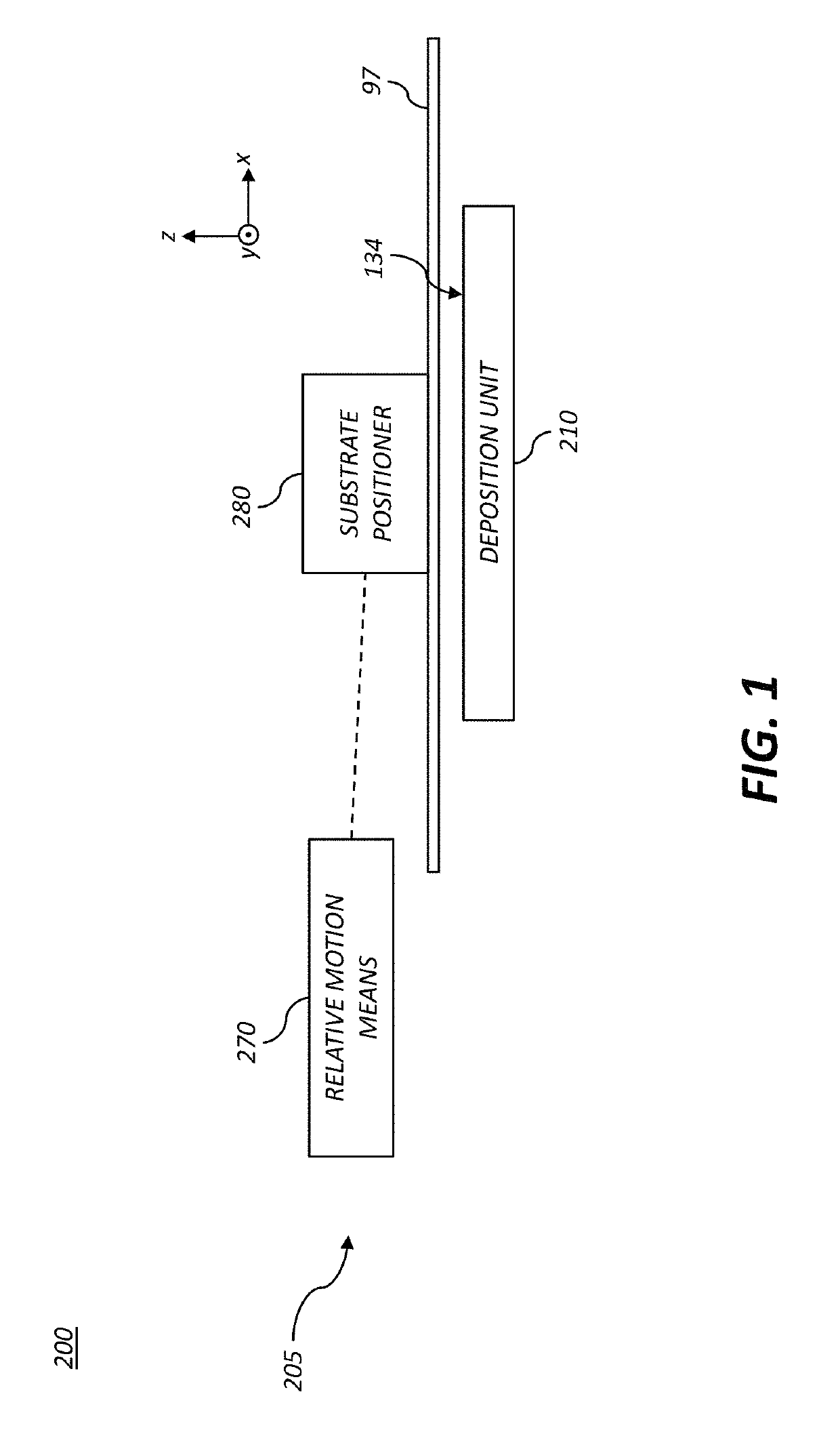
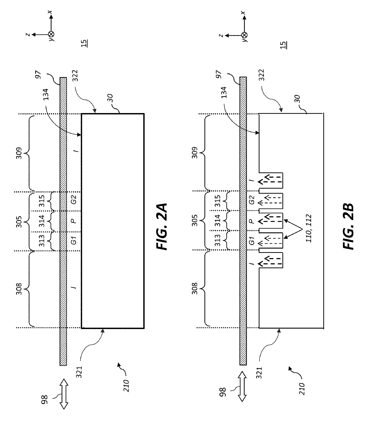
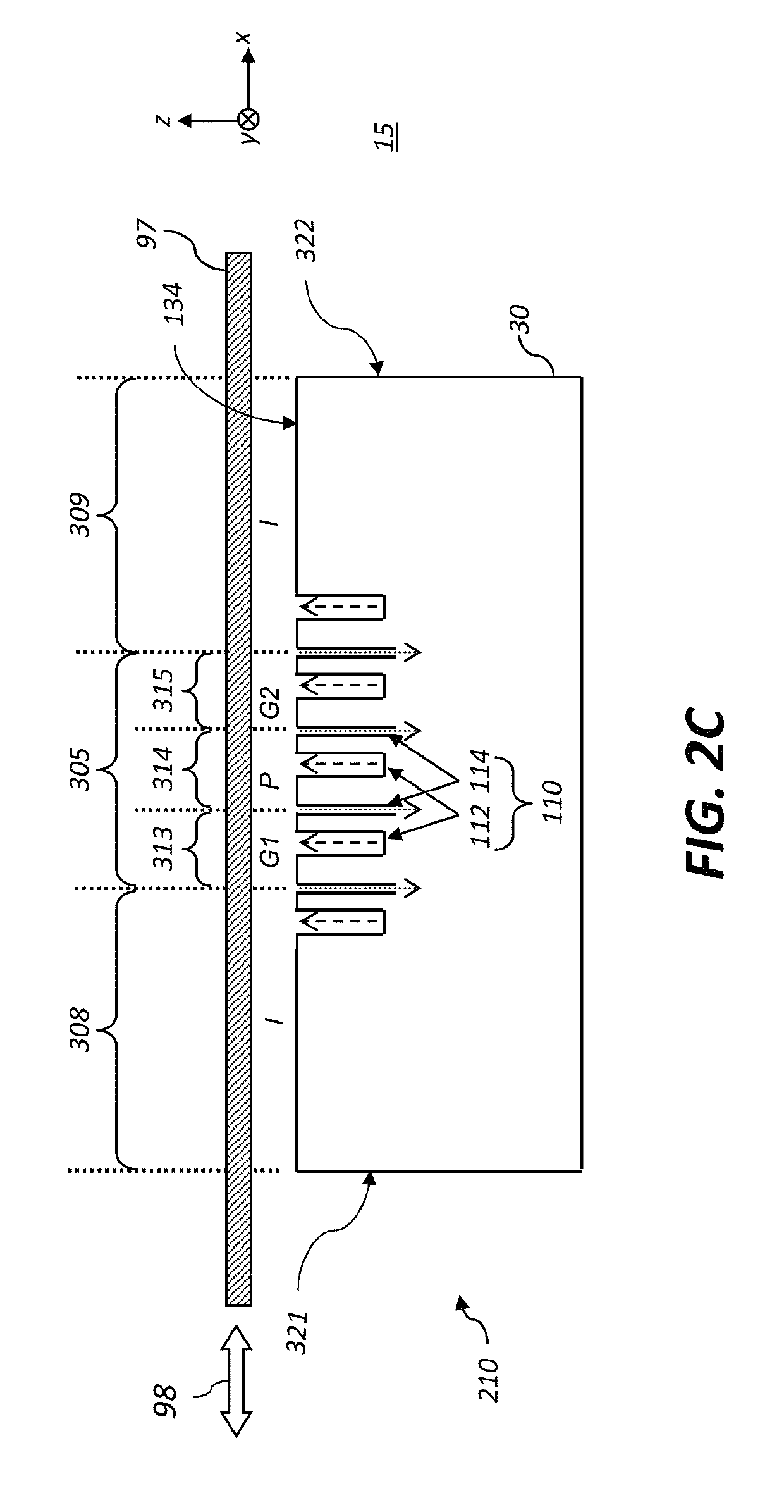
A material deposition system for depositing a material on a surface of a substrate includes a deposition head having an output face configured to simultaneously supply a plurality of gaseous materials in a sequence of gas zones. The gas zones include a deposition zone located between first and second inert zones. The deposition zone includes a first reactant zone adjacent to the first inert zone, a last reactant zone adjacent to the second inert zone, and one or more purge gas zones. A motion actuator moves a substrate over the output face with a repeating motion profile that prevents a region of active deposition on the substrate from being exposed to the external environment prior to having achieved a final material deposition amount. The repeating motion profile include a forward motion portion and a backward motion portion which is less than the forward distance by an ooch distance.

Description

CROSS-REFERENCE TO RELATED APPLICATIONS[0001]Reference is made to commonly assigned, co-pending U.S. patent application Ser. No. 15 / 458,235, entitled “Modular thin film deposition system,” by Spath et al.; to commonly assigned, co-pending U.S. patent application Ser. No. 15 / 458,250, entitled “Deposition system with vacuum pre-loaded deposition head,” by Spath et al.; to commonly assigned, co-pending U.S. patent application Ser. No. 15 / 458,262, entitled “Dual gas bearing substrate positioning system,” by Spath; to commonly assigned, co-pending U.S. patent application Ser. No. 15 / 458,270, entitled “Deposition system with moveable-position web guides,” by Spath et al,; to commonly assigned, co-pending U.S. patent application Ser. No. 15 / 458,297, entitled “Deposition system with modular deposition heads,” by Spath et al.; to commonly assigned, co-pending U.S. patent application Ser. No. 15 / 458,307, entitled “Porous gas-bearing backer,” by Spath; to commonly assigned, co-pending U.S. pat...

Claims


Application Information

Patent Timeline
Patent Type & Authority Patents(United States)
IPC IPC(8): C23C16/455C23C16/52C23C16/44
CPCC23C16/45544C23C16/52C23C16/4412C23C16/45551C23C16/45555C23C16/45531C23C16/545
Inventor SPATH, TODD MATHEWTUTT, LEE WILLIAMELLINGER, CAROLYN RAENELSON, SHELBY FORRESTER
Owner EASTMAN KODAK CO
Learn More