
Optical cable wiring system and optical cable connecting component

a technology of optical cable and connecting component, applied in the field of optical fibre communications, can solve the problems of municipal eyesores, waste of optical cable, complex situation,

Active Publication Date: 2019-10-15
COMMSCOPE TELECOMM (SHANGHAI) CO LTD
View PDF102 Cites 6 Cited by
  • Summary
  • Abstract
  • Description
  • Claims
  • Application Information

AI Technical Summary

Benefits of technology

[0011]One aim of this invention is to provide a type of optical cable connecting assembly and a type of optical cable wiring system, capable of reducing the laying length of single core distribution optical cables connected to user terminals, thus reducing material and labour costs, in addition to improving municipal aesthetics.
[0018]According to another exemplary embodiment of this invention, there is also a second catching slot formed on the internal wall of the second end of said base, there being a block shaped flange formed on said strain relief boot, said block shaped flange catching in said second catching slot, thus securing said strain relief boot to the base of said housing.
[0023]According to another exemplary embodiment of this invention, there is a first catching slot formed on the internal wall of the second end of said base; said optical cable fan-out further including a retainer, for holding the multiple branch adapter optical cables together; additionally, said retainer catching in said first catching slot, thus securing the multiple branch adapter optical cables to the base of said housing.
[0025]According to another exemplary embodiment of this invention, there is a second catching slot formed on the internal wall of the second end of said base; there being a block shaped flange formed on said strain relief boot, said block shaped flange catching in said second catching slot, thus securing the strain relief boot to the base of said housing.
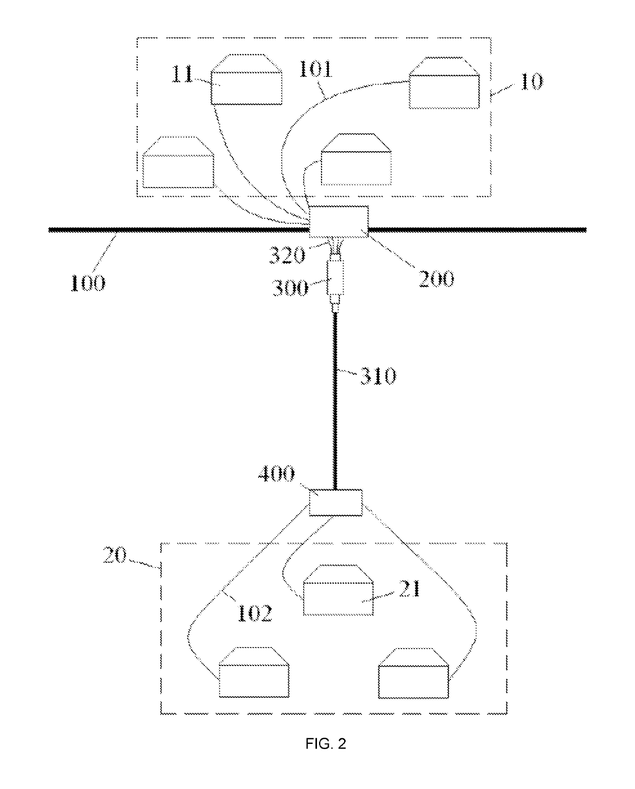
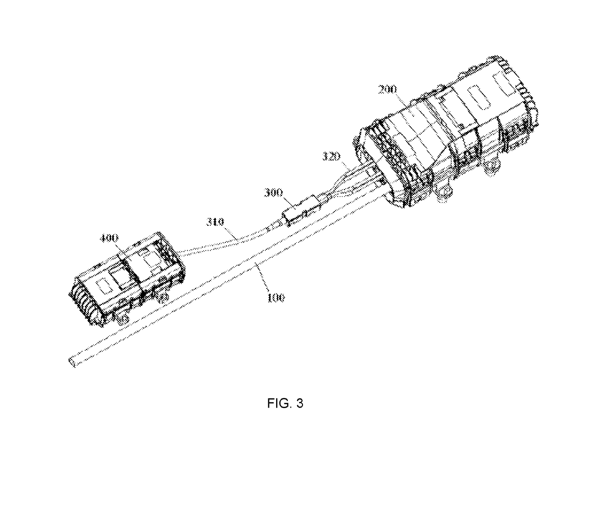
[0027]In the optical cable connecting assembly and optical cable wiring system according to the various embodiments of this invention, the main optical cable disposed near the first user zone can be connected to a second optical cable connector box near the second user zone disposed at a distance from the first user zone via a first optical cable connector box disposed near the first user zone, an optical cable fan-out and a single main adapter optical cable. In this manner, it becomes unnecessary to lay multiple single core distribution optical cables over long distances between the first user zone and second user zone, thus reducing the laying length of single core distribution optical cable required for connecting to the second user zone at a distance from the main optical cable, reducing material and labour costs, and also improving municipal aesthetics.

Problems solved by technology

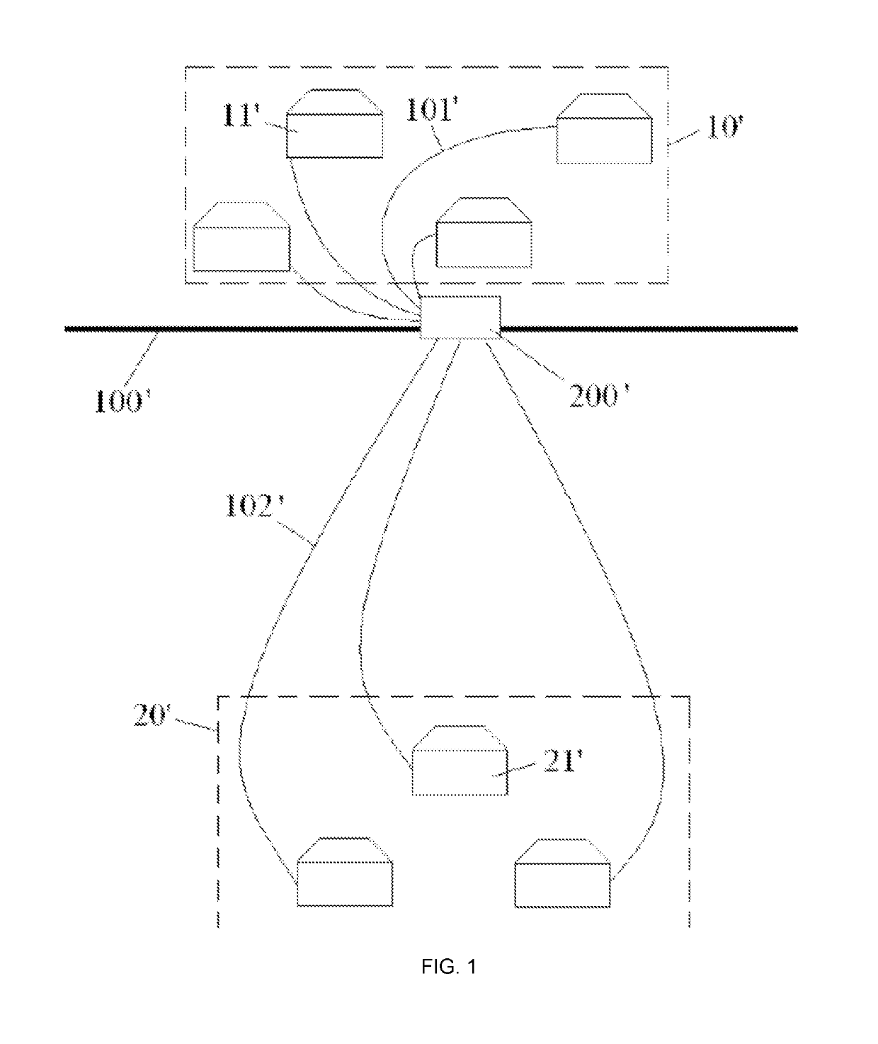
But, when it is necessary to connect optical fibres to various second user terminals 21′ in a second user zone 20′ at a distance from the first user zone 10′, the situation becomes more complex and problematic.
As shown in FIG. 1, due to there being a relatively great distance between the second user zone 20′ and the first user zone 10′, the multiple single core second distribution optical cables 102′ need to be laid over relatively great distances, which results in a waste of optical cable, and additionally, the multiple loose single core second distribution optical cables 102′ look disordered, causing a municipal eyesore.
Apart from this, if accounts relating to the various second user terminals 21′ within the second user zone 20′ are opened at different times, it will be necessary to lay single core second distribution optical cables 102′ over long distances on multiple occasions, resulting in increased labour costs.

Method used


Image

  • Optical cable wiring system and optical cable connecting component
  • Optical cable wiring system and optical cable connecting component
  • Optical cable wiring system and optical cable connecting component

Examples


Embodiment Construction

[0033]The following embodiments, taken in conjunction with the drawings, provide a more detailed description of the technical schemes of this invention. Within the Description, numbering that is the same or similar in the drawings refers to components that are the same or similar. The aim of the following description of the modes of implementation of this invention taken in conjunction with the drawings is to explain the general inventive concept of this invention, and should not be understood as restricting this invention.

[0034]Apart from that, in the following detailed descriptions, for convenience of interpretation, many specific details are described in order to allow a full understanding of the disclosed embodiments. It should be clear that, one or more embodiments could be implemented without these specific details. In all other cases, structures and apparatuses which are common knowledge are represented graphically to simplify the drawings.

[0035]According to the general techn...


PUM


Abstract

This invention discloses a type of optical cable wiring system, including: a main optical cable, first optical cable connector box and optical cable fan-out disposed near a first user zone; a second optical cable connector box disposed at a distance from the first user zone and near a second user zone; and a single main adapter optical cable disposed between the first optical cable connector box and second optical cable connector box. An optical cable fan-out converts a single main adapter optical cable to multiple branch adapter optical cables. Multiple branch adapter optical cables are connected to the main optical cable via a first optical cable connector box; multiple first distribution optical cables for the purpose of connection to a first user zone are connected to a main optical cable via a first optical cable connector box; multiple first distribution optical cables for the purpose of connection to a second user zone are connected to a single main adapter optical cable via a second optical cable connector box. In this manner, it becomes unnecessary to lay multiple second distribution optical cables over long distances between the first user zone and second user zone, thus reducing the laying length of second distribution optical cables, reducing material and labor costs, and additionally improving municipal aesthetics.

Description

CROSS-REFERENCE TO RELATED APPLICATION[0001]This application is a National Stage Application of PCT / CN2015 / 095146, filed on 20 Nov. 2105, which claims the benefit of Serial No. 201410673296.3, filed on 21 Nov. 2014 in China and which applications are incorporated herein by reference. To the extent appropriate, a claim of priority is made to each of the above disclosed applications.TECHNICAL FIELD[0002]This invention relates to the field of optical fibre communications, and to be more specific, relates to a fibre to the home optical cable connecting assembly and a fibre to the home optical cable wiring system.BACKGROUND OF THE INVENTION[0003]FIG. 1 shows a fibre to the home optical cable wiring system of the prior art.[0004]As shown in FIG. 1, in the prior art, fibre to the home optical cable wiring systems generally include a main optical cable 100′, an optical cable junction box 200′ and multiple single core distribution optical cables 101′ and 102′. The multiple single core distri...

Claims


Application Information

Patent Timeline
Patent Type & Authority Patents(United States)
IPC IPC(8): G02B6/46G02B6/38G02B6/44
CPCG02B6/46G02B6/4446G02B6/4472G02B6/4476G02B6/4477G02B6/38G02B6/44
Inventor WANG, ZHENGBINCAI, ZHAOHUILIU, YANXU, DONG
Owner COMMSCOPE TELECOMM (SHANGHAI) CO LTD
Learn More