Mixing line

A technology of mixing materials and fodder, which is applied in the direction of mixers, applications, gardening, etc., can solve the problem of long length of mixing line, and achieve the effect of improving mixing effect, reducing occupation and reducing laying length

Active Publication Date: 2020-09-08
ZHEJIANG HONGYE EQUIP TECH
View PDF9 Cites 0 Cited by
  • Summary
  • Abstract
  • Description
  • Claims
  • Application Information

AI Technical Summary

Problems solved by technology

[0004] In the above mixing line, the feeding device, feeding device, covering device and discharging dev

Method used


Image

  • Mixing line
  • Mixing line
  • Mixing line

Examples


Embodiment 1

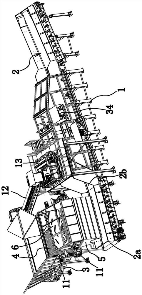
[0045] Such as figure 1 As shown, the mixing line includes a frame 1, a forage breaking mechanism, an auxiliary material breaking mechanism, a mixing mechanism for mixing forage and auxiliary materials, and a main conveyor belt 2 arranged on the frame 1, and the forage breaking mechanism The auxiliary material dispersing mechanism and the material mixing mechanism are distributed sequentially along the conveying direction of the main conveyor belt 2 .

[0046] Wherein, the main conveyor belt 2 is composed of a horizontal section 2a and an inclined section 2b, the horizontal section 2a and the inclined section 2b are continuously distributed along the conveying direction of the main conveyor belt 2, and the inclined section 2b is arranged obliquely upward relative to the horizontal section 2a. The forage breaking mechanism is arranged on one side of the horizontal section 2a, and the outlet of the forage breaking mechanism is directly above the belt surface of the horizontal se...

Embodiment 2

[0064] The structure and principle of this second embodiment are basically the same as that of the first embodiment. The difference is that the frame 1 includes an internally threaded pipe whose axis extends along the conveying direction of the side conveyor belt 12. There are two internally threaded pipes located at the conveying On both sides of the belt, a rod body is inserted into the two internally threaded pipes. The outer end of the rod protrudes from the internally threaded pipe and is fixedly connected with the baffle 17. The locking piece 21 is an external thread formed on the rod body, and the rod body and the internally threaded pipe pass through the internal thread Connected with external thread engagement.


PUM


Abstract

The invention provides a mixing line, and belongs to the technical field of machinery. The mixing line comprises a rack, a forage scattering mechanism, a main conveying belt arranged on the rack, a mixing mechanism and an auxiliary material scattering mechanism, the mixing mechanism and the auxiliary material scattering mechanism are both arranged on the main conveying belt, the main conveying belt is composed of a horizontal section and an inclined section, the horizontal section and the inclined section are continuously distributed in the conveying direction of the main conveying belt, and the inclined section is arranged obliquely upwards relative to the horizontal section; and the forage scattering mechanism is arranged on one side of the horizontal section, the forage scattering mechanism, the auxiliary material scattering mechanism and the mixing mechanism are sequentially distributed in the conveying direction of the main conveying belt, discharge ports of the forage scatteringmechanism and the auxiliary material scattering mechanism are respectively positioned right above the horizontal section belt surface and the inclined section belt surface, the mixing mechanism is arranged on the inclined section, a second side conveying belt which is obliquely arranged upwards is further arranged on the rack, the second side conveying belt and the forage scattering mechanism arelocated on the same side, and the second side conveying belt can convey auxiliary materials to a feeding port of the auxiliary material scattering mechanism. The mixing line is short in length.

Description

technical field [0001] The invention belongs to the technical field of machinery and relates to a material mixing line. Background technique [0002] At present, many fungi completely rely on the nutrients in the medium for growth and development. The existing culture medium for bacteria is generally composed of forage and auxiliary materials. The auxiliary materials generally include a mixture of chicken manure, limestone, soil, etc., and the forage and auxiliary materials are mixed by adding water. The existing culture medium is generally completed by artificial cultivation, and the whole process is inefficient and consumes a lot of manpower. [0003] In response to the above problems, the applicant has realized the shortcomings, and proposed a mixing line (application number: 201610044911.3), including a frame, a feeding device, and the feeding device includes a workbench and a transmission assembly arranged on the frame 1. The feeding device, the feeding device include...

Claims


Application Information

Patent Timeline
IPC IPC(8): B01F13/10B01F15/00B01F15/02A01G18/22
CPCA01G18/22B01F33/821B01F33/86B01F35/00B01F35/322B01F35/31B01F35/30B01F35/3215B01F35/43B01F35/3204B01F35/71B01F35/71705B01F35/754
Inventor 颜卫兵张晓召潘敏超颜俊俊张育青徐荣宾
Owner ZHEJIANG HONGYE EQUIP TECH
Why Eureka
Try Eureka