Supercharge Your Innovation With Domain-Expert AI Agents!

Image forming apparatus and control program

a technology of image forming apparatus and control program, which is applied in the direction of electrographic process apparatus, instruments, optics, etc., can solve the problems of cracks, techniques that do not describe about cracks, and the surface layer gradually degrades

Active Publication Date: 2019-10-15
KONICA MINOLTA INC
View PDF7 Cites 2 Cited by
  • Summary
  • Abstract
  • Description
  • Claims
  • Application Information

AI Technical Summary

Benefits of technology

Accurately detects cracks in the charging roller, preventing image defects and ensuring timely replacement, thereby improving the reliability and efficiency of the image forming process.

Problems solved by technology

The stress variation affects the surface layer of the charging roller, so that the surface layer gradually degrades, eventually breaks, and crack occurs.
However, the technique does not describe about a crack.
Further, even if the technique disclosed in JP 11-352754 A is used to detect a crack in the charging roller, there is a problem that it is difficult to discriminate between a change of the surface condition of the charging roller due to dirt, scratch, or the like and a change of the surface condition of the charging roller due to a crack.

Method used


Image

  • Image forming apparatus and control program
  • Image forming apparatus and control program
  • Image forming apparatus and control program

Examples


Embodiment Construction

[0039]Hereinafter, an embodiment of the present invention will be described in detail with reference to the drawings. However, the scope of the invention is not limited to the illustrated examples. The same or corresponding portions in the drawings are denoted by the same reference numerals and the description thereof will not be repeated.

[0040][A. Outline]

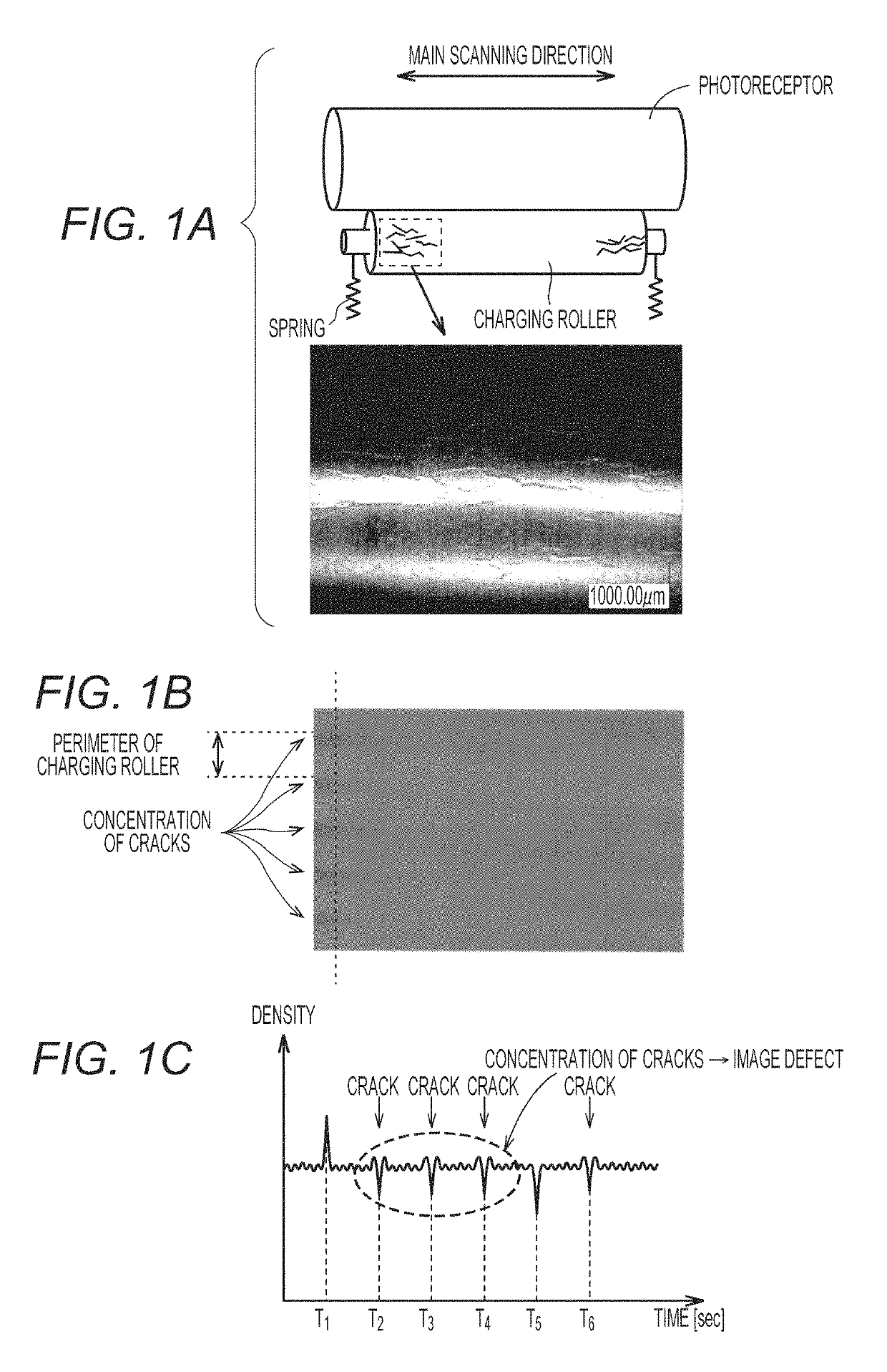
[0041]FIGS. 1A to 1C are diagrams for explaining an outline of an image forming apparatus according to the embodiment. Referring to FIG. 1A, a charging roller is arranged to be in contact with a photoreceptor and configured to be driven to rotate according to rotation of the photoreceptor. Therefore, when paying attention to a local region of the charging roller, a stress generated in the local region changes when the local region comes into contact with the photoreceptor and when the local region detaches from the photoreceptor. The variation of the stress is repeated, so that a crack occurs on the surface of the charging roller....


PUM


Abstract

An image forming apparatus includes: an image carrier that carries and transports a latent image; a charging member that is arranged to be in contact with a surface of the image carrier; a developing device that supplies toner to the image carrier and forms a toner image; a density detection unit that detects a density of the toner image; a pattern detection unit that detects a predetermined density variation pattern based on a detection result of the density detection unit according to the toner image; and a determination unit that determines a state of the charging member based on the number of the predetermined density variation patterns detected within a predetermined period of time.

Description

[0001]The entire disclosure of Japanese Patent Application No. 2016-098588 filed on May 17, 2016 including description, claims, drawings, and abstract are incorporated herein by reference in its entirety.BACKGROUND OF THE INVENTIONField of the Invention[0002]The present disclosure relates to an image forming apparatus, and more specifically to an image forming apparatus according to an electrophotographic method.Description of the Related Art[0003]In an image forming apparatus according to an electrophotographic method, as a means for charging a photoreceptor, a non-contact charging method using corona discharge or the like and a contact charging method using a charging roller or the like are known. In recent years, from a viewpoint of energy saving, the contact charging method is more widely prevalent than the non-contact charging method.[0004]The charging roller used for the contact charging method is arranged to be in contact with the photoreceptor and configured to be driven to ...

Claims


Application Information

Patent Timeline
Patent Type & Authority Patents(United States)
IPC IPC(8): G03G15/00G03G15/06
CPCG03G15/0216G03G15/5041G03G15/5058G03G15/553G03G15/556G03G15/065
Inventor WATANABE, TOSHIFUMI
Owner KONICA MINOLTA INC
Features
  • R&D
  • Intellectual Property
  • Life Sciences
  • Materials
  • Tech Scout
  • Unparalleled Data Quality
  • Higher Quality Content
  • 60% Fewer Hallucinations
Learn More