Method for producing an improved filter for injectors of fuel, oils, solutions, additives and fluids in general, and filter thus produced

a technology of filter and fuel, applied in the direction of filtration separation, machines/engines, separation processes, etc., can solve the problems of braking system impurities, high content of unburnt particles in the circulating fluid, and unsatisfactory combustion of fuel, so as to achieve greater mechanical rigidity, reduce production costs, and protect the effect of the whole system

Active Publication Date: 2019-10-22
GVS SPA
View PDF8 Cites 0 Cited by
  • Summary
  • Abstract
  • Description
  • Claims
  • Application Information

AI Technical Summary

Benefits of technology

[0015]Finally, the positioning of the filter element in the mould for the purpose of overmoulding with the plastic material requires particular attention, in order to maintain a desired configuration of the filter element while preventing its crushing during the movement and moulding of this material, and to prevent the deposition of impurities, dust or other substances on said filter element during its movement towards the mould.DESCRIPTION OF THE INVENTION
[0016]The object of the present invention is to provide a method for producing a filter for injectors of fuel, oils, solutions, fluid additives in general whether liquid or gaseous, and for systems such as braking systems, in particular those of the ABS type, and transmission systems, and for producing a filter of this type which is improved relative to known production processes and filters and which can overcome the aforementioned drawbacks of these solutions.
[0017]In particular, an object of the invention is to provide a filter of the aforesaid type which has lower production costs, the manipulation of which filter is limited in the course of its production and simplified after its production.
[0018]Another object is that of providing a filter of the aforesaid type in which the filter element has greater mechanical rigidity and total protection from external impact, relative to the known solutions.

Problems solved by technology

This is done in order to arrest and capture any impurity present in the fluid (fuel or additive, for example) circulating in the conduit before it reaches the injectors, as this could cause known problems: for example, in a diesel engine, the injectors might become partially blocked, resulting in imperfect combustion of the fuel and the consequent discharge of fumes with a high content of unburnt particles from the system concerned.
A similar problem, namely the presence of impurities in the circulating fluid, is present in braking systems, particularly those of the ABS type, said problem being resolved, as in the aforesaid systems for supplying fuel to injectors, by placing filters in the brake fluid conduits to capture the aforesaid impurities.
Finally, problems with impurities have also been present in the oil of transmission systems (in dual-clutch transmissions, for example), where the aforesaid impurities could interfere with the correct operation of the gearing, thereby preventing the safe and correct use of the vehicle or device comprising this system.
Similar problems are present in supply lines for the circulation of gases, such as gases for medical use (oxygen, for example) or other fluids (such as water), where the fluid is required to be particularly pure for the purposes of its use downstream of the filter (for example, during the production of beverages such as beer).

Method used


Image

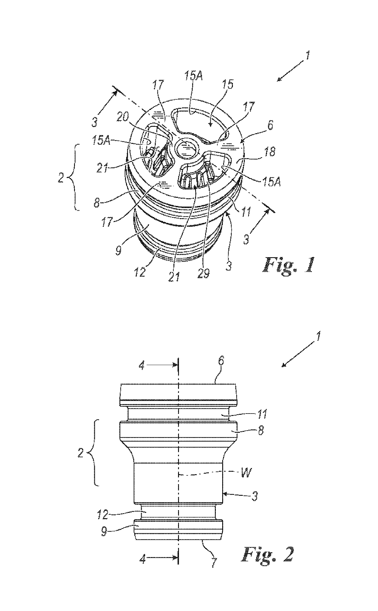
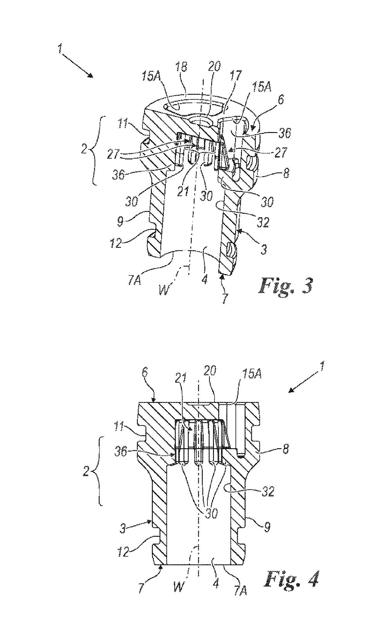
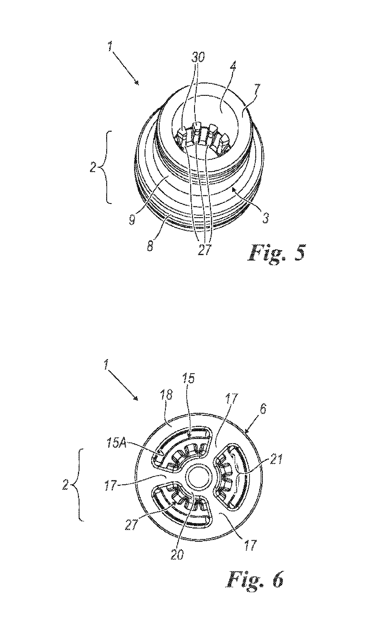
  • Method for producing an improved filter for injectors of fuel, oils, solutions, additives and fluids in general, and filter thus produced
  • Method for producing an improved filter for injectors of fuel, oils, solutions, additives and fluids in general, and filter thus produced
  • Method for producing an improved filter for injectors of fuel, oils, solutions, additives and fluids in general, and filter thus produced

Examples


Embodiment Construction

[0016]The object of the present invention is to provide a method for producing a filter for injectors of fuel, oils, solutions, fluid additives in general whether liquid or gaseous, and for systems such as braking systems, in particular those of the ABS type, and transmission systems, and for producing a filter of this type which is improved relative to known production processes and filters and which can overcome the aforementioned drawbacks of these solutions.

[0017]In particular, an object of the invention is to provide a filter of the aforesaid type which has lower production costs, the manipulation of which filter is limited in the course of its production and simplified after its production.

[0018]Another object is that of providing a filter of the aforesaid type in which the filter element has greater mechanical rigidity and total protection from external impact, relative to the known solutions.

[0019]A further object of the invention is that of providing a filter of the aforesa...


PUM

PropertyMeasurementUnit
shapeaaaaaaaaaa
surface areaaaaaaaaaaa
cylindrical shapeaaaaaaaaaa

Abstract

Method for producing a filter for injectors of fuel, oil, solutions, additives and fluids in general, for example for braking and transmission systems. The filter including an element of plastic material and having a tubular shape, open at opposite ends, internally hollow and having on one wall of its internal cavity a plurality of projections spaced apart from one another. These projections interacting with portions of a filter element of the pleated type associated with this tubular element and capable of filtering the fluid circulating through the tubular element. The filter element and the tubular element to form a single filter body by being co-moulded, the filter element being incorporated and completely positioned within the tubular element, but having portions of filter surface area free of this tubular element to allow passage and filtration of circulating fluid.

Description

CROSS-REFERENCE TO RELATED APPLICATIONS[0001]This is a § 371 National Stage Application of International Application No. PCT / IB2015 / 057152 filed on Sep. 17, 2015, claiming the priority of Italian Patent Application No. MI2014A001640 filed on Sep. 22, 2014.FIELD OF THE INVENTION[0002]The present invention relates to a method for producing a filter for injectors of fuel, oils, solutions, additives and fluids in general, and for systems such as braking and transmission systems, and to a filter thus produced, according to the preambles of the principal claims.BACKGROUND OF THE INVENTION[0003]The present description is provided with reference to the filtration of liquids such as fuels or oils for applications in vehicles or industrial machinery. However, the invention is also applicable to the field of the filtration of fluids in general, including liquids such as water and gases such as gases for medical use.[0004]As is known, in internal combustion engines having any kind of fuel suppl...

Claims


Application Information

Patent Timeline
Patent Type & Authority Patents(United States)
IPC IPC(8): F02M61/16B01D29/31B01D29/11B01D39/16
CPCB01D29/111F02M61/165B01D39/16B01D29/31B01D2201/12B01D35/005
Inventor SCAGLIARINI, MARCO
Owner GVS SPA
Why Eureka
Try Eureka