
Technique for signalling congestion in a packet communication network

a packet communication network and packet communication technology, applied in the field of packet communication networks, can solve the problems of delay in the signaling, delay in the transmitter taking measures to prevent or resolve congestion, and the equipment situated on the path can be affected by congestion, so as to reduce the bit rate of the transmitted stream, prevent or resolve congestion, and reduce the bit rate

Active Publication Date: 2019-10-22
ORANGE SA (FR)
View PDF11 Cites 0 Cited by
  • Summary
  • Abstract
  • Description
  • Claims
  • Application Information

AI Technical Summary

Benefits of technology

The patent describes a method for managing congestion in a network by allowing a node to send information about congestion to a transmitter of another stream. This allows the transmitter to take measures to prevent or resolve the congestion, such as reducing the bit rate of the transmitted stream. The method also allows prioritization of streams based on their importance or the importance of the user or service they belong to. The method ensures that the quality of service and experience of users are preserved, and it reduces the risk of losing the congestion information. The method can be easily deployed and compatible with various data transfer protocols. The method also allows for retrieving congestion information from data packets of the second stream, providing an indication of an almost real-time state of congestion.

Problems solved by technology

Congestion can occur on any equipment situated on the path taken by a packet.
This causes a delay in the signaling of the congestion to the transmitter and thus in the processing thereof.
This also results in a delay in the transmitter taking measures to prevent or resolve the congestion.
It is furthermore the case that congestion can cause a deterioration in the quality of service.
By way of example, this deterioration translates into a loss of data packets, or an increase in the latency relating to the sending of the data packets from a transmitting node to a receiving node.

Method used


Image

  • Technique for signalling congestion in a packet communication network
  • Technique for signalling congestion in a packet communication network
  • Technique for signalling congestion in a packet communication network

Examples


Embodiment Construction

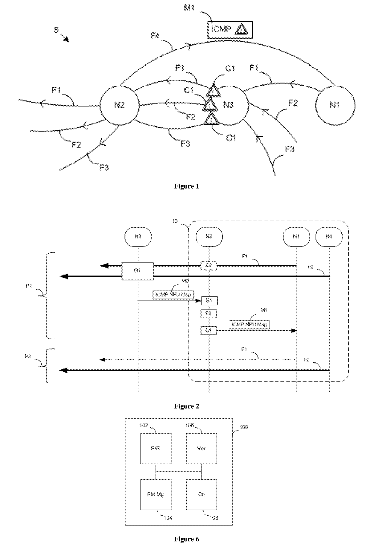
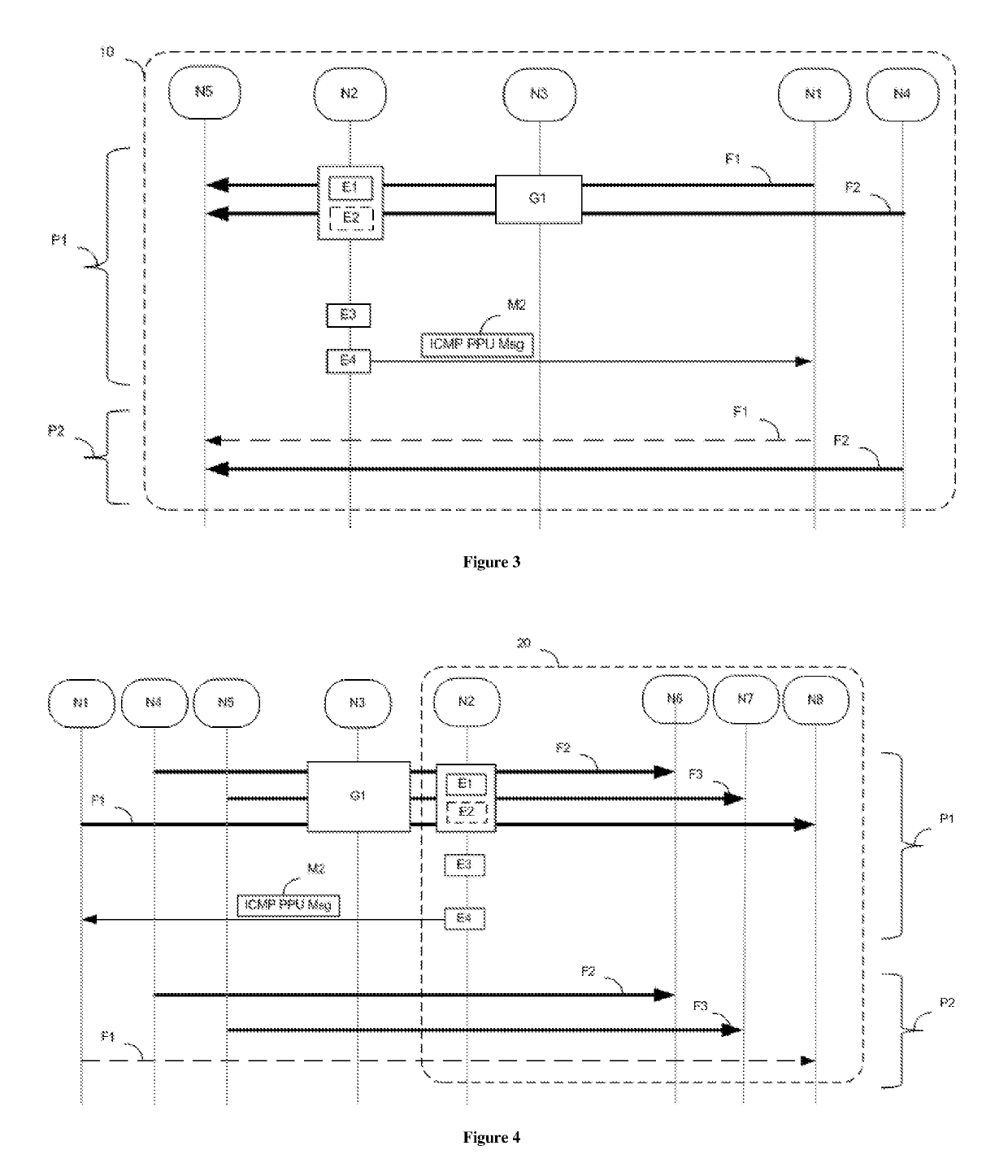
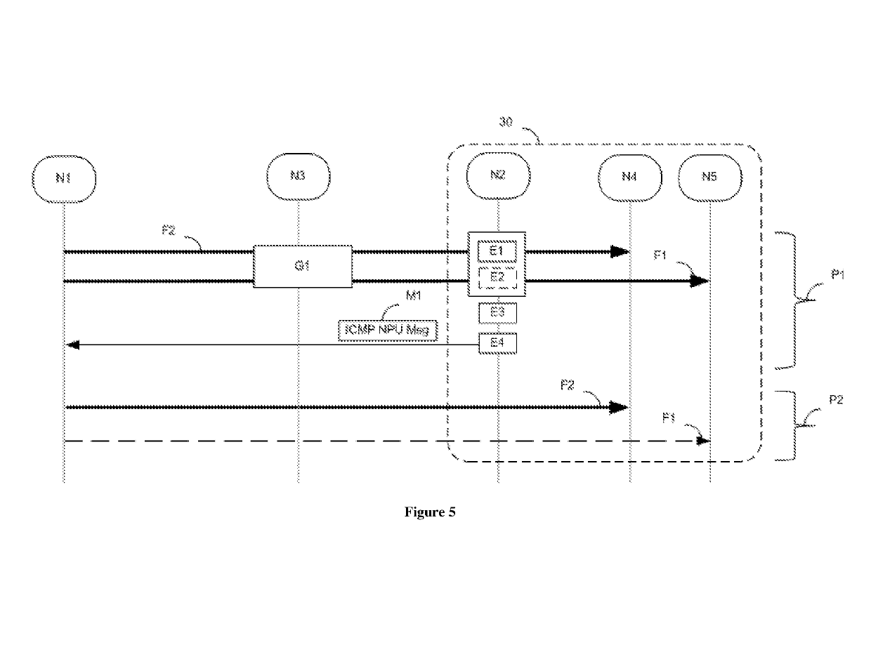
[0041]FIG. 1 shows a system for signaling a piece of congestion information in a communication network 5 according to a particular embodiment. The communication network 5 is particularly a packet communication network. The system comprises three nodes N1, N2 and N3. A node is defined as an element involved in a service chain of a network. By way of nonlimiting example, it is physical equipment of a network (e.g. switch, router, firewall, GGSN, for “Gateway GPRS Support Node”) or even elements of a data processing center, “Data Center” (e.g. interconnection manager or “DCI manager”, for “Data Center Interconnection Manager”, operating system, controller). By way of illustrative example, the node N1 provides a file transfer service and the nodes N2 and N3 are routers.

[0042]The nodes N2 and N3 convey packets transmitted in one plane, referred to as transfer plane. Three streams F1, F2 and F3 of data packets are shown. More precisely, a stream is a succession of packets transmitted betw...


PUM


Abstract

A method for signaling a piece of congestion information regarding a first data stream routed by a first node in a network. The method includes the following acts implemented by a second node via which the first data stream and at least a second data stream are routed: obtaining a piece of congestion information regarding the second data stream, the congestion information indicating that a third node, via which the first data stream is routed, has detected a congestion situation for a routing of the second stream in a data transfer plane; checking that the first data stream has a priority level lower than that of the second data stream; and sending, to the first node, a control message in a control plane, the control message carrying the congestion information.

Description

CROSS-REFERENCE TO RELATED APPLICATIONS[0001]This application is a Section 371 National Stage Application of International Application No. PCT / FR2014 / 053362, filed Dec. 16, 2014, the content of which is incorporated herein by reference in its entirety, and published as WO 2015 / 092260 on Jun. 25, 2015, not in English.FIELD OF THE DISCLOSURE[0002]The invention lies in the field of packet communication networks and more particularly concerns a technique for signaling congestion from one node in a communication network to another node in this network.BACKGROUND OF THE DISCLOSURE[0003]Congestion can occur on any equipment situated on the path taken by a packet. More precisely, a piece of equipment can be congested at input or output memories, internal queues, etc.[0004]Congestion notification functions have been defined by standardization organizations for packet communication networks. These functions are based on various mechanisms, among which there may be cited an explicit congestion...

Claims


Application Information

Patent Timeline
Patent Type & Authority Patents(United States)
IPC IPC(8): H04L12/26H04L12/801H04L12/851
CPCH04L47/33H04L47/11H04L47/24
Inventor ELLOUZE, SELIMSTEPHAN, EMILEMARJOU, XAVIER
Owner ORANGE SA (FR)
Learn More