Liquid ejecting head and liquid ejecting apparatus
a liquid ejecting head and liquid ejecting technology, which is applied in the direction of printing, inking apparatus, etc., can solve the problems of reducing the reliability of the liquid ejecting head, warpage of the liquid ejecting head, and the inability to form all the plates, so as to reduce the reliability of the liquid ejecting apparatus.
- Summary
- Abstract
- Description
- Claims
- Application Information
AI Technical Summary
Benefits of technology
Problems solved by technology
Method used
Image
Examples
second embodiment
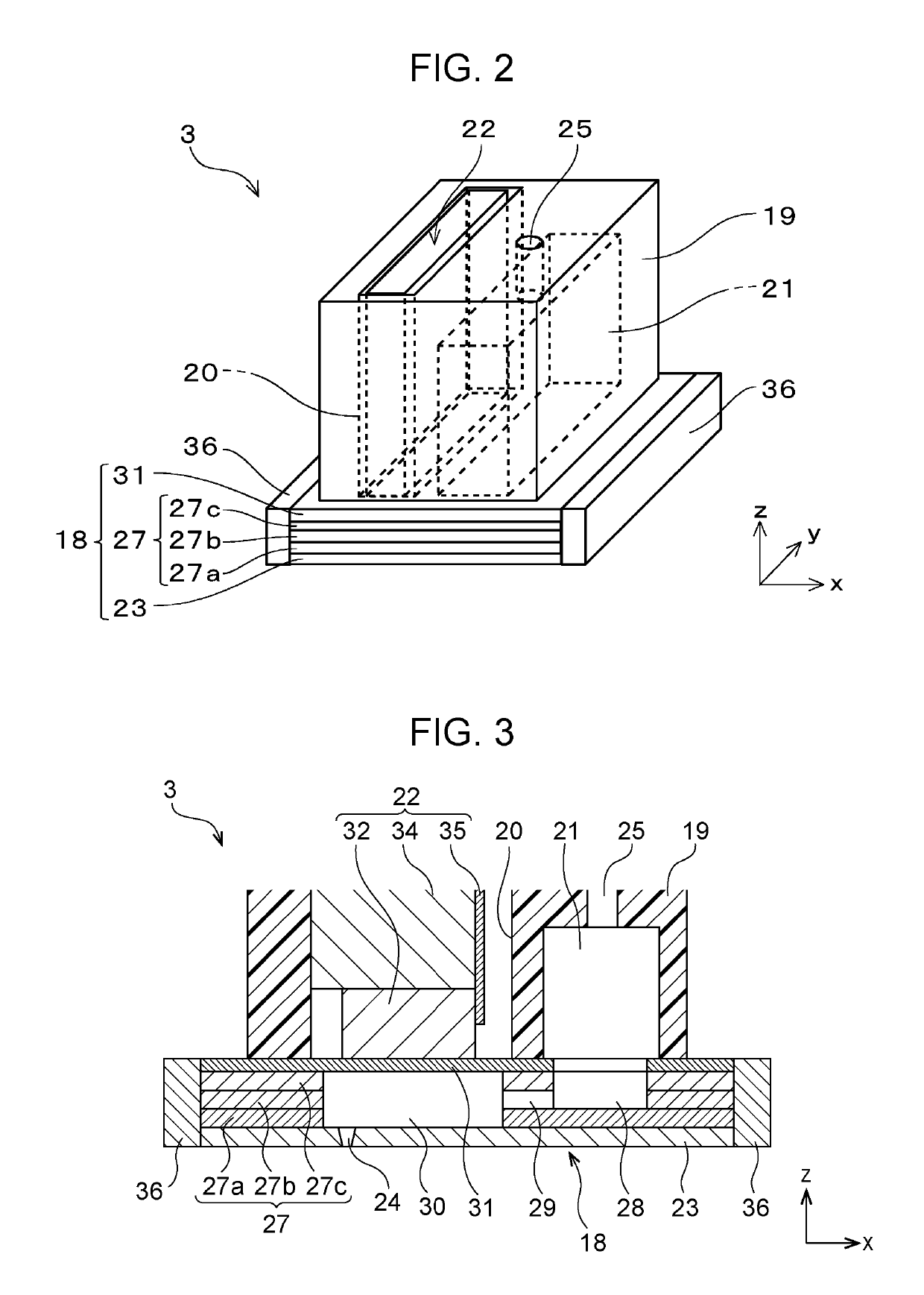
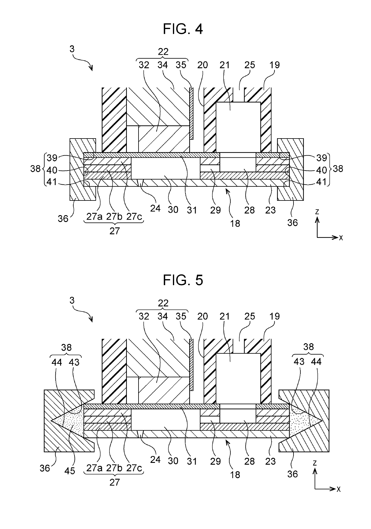
[0043]A holding member 36 according the second embodiment illustrated in FIG. 4 includes a recessed portion 38 in which an end portion (that is, a section including the end surface) of the flow path member 18 is accommodated. In other words, the holding member 36 according to the embodiment includes the recessed portion 38 that has a thickness (dimension in the z direction) greater than that of the flow path member 18, and the surface that faces the end surface of the flow path member 18 in the central portion in the thickness direction is recessed to the middle of the holding member 36 in the widthwise direction (x direction). The recessed portion 38 according to the embodiment has a first surface 39 that faces the upper surface of the flow path member 18 and is parallel to the upper surface, a second surface 40 that faces the end surface of the flow path member 18 and is parallel to the end surface, and a third surface 41 that faces the lower surface of the flow path member 18 and...
first embodiment
[0045]In this embodiment, since the end portions of the flow path member 18 are fit into the recessed portions 38 of the holding members 36, the holding members 36 can suppress the thermal expansion of the flow path member 18 in the plate-stacking direction (z direction). As a result, when the temperature of the flow path member 18 rises, forces are applied toward the inside in the plate-stacking direction, that is, in the directions of holding the flow path member 18. With this structure, the adhesive that bonds the flow path plate 27 and the nozzle plate 23 and the adhesive that bonds the flow path plate 27 and the diaphragm 31 can be further prevented from peeling off. The other structures are similar to those in the first embodiment, and accordingly, their descriptions are omitted.
third embodiment
[0046]A holding member 36 illustrated in FIG. 5 has a recessed portion 38 in which surfaces are inclined with respect to the end surface of the flow path member 18. Specifically, the recessed portion 38 in the holding member 36 according to the embodiment has a first inclined surface 43 that is inclined downward from the upper surface of the flow path member 18 in a direction away from the flow path member 18 and a second inclined surface 44 that is inclined upward from the lower surface of the flow path member 18 in a direction away from the flow path member 18. In other words, the recessed portion 38 is open toward the end surface of the flow path member 18. The end portion of the flow path member 18 is held between the first inclined surface 43 and the second inclined surface 44 in the recessed portion 38. In this embodiment, a filler 45 is filled in a space between the end surface of the flow path member 18 and the surfaces, which face the end surface, in the recessed portion 3...
PUM
 Abstract
Description
Claims
Application Information
 - R&D
- Intellectual Property
- Life Sciences
- Materials
- Tech Scout
- Unparalleled Data Quality
- Higher Quality Content
- 60% Fewer Hallucinations
Browse by: Latest US Patents, China's latest patents, Technical Efficacy Thesaurus, Application Domain, Technology Topic, Popular Technical Reports.
© 2025 PatSnap. All rights reserved.Legal|Privacy policy|Modern Slavery Act Transparency Statement|Sitemap|About US| Contact US: help@patsnap.com


