Image reading apparatus

a technology of image reading and reading cylinder, which is applied in the direction of electrical devices, thin material handling, article separation, etc., can solve the problems of thin paper being likely to be caught by the opening of the concave portion, and causing jamming

Active Publication Date: 2019-11-19
SEIKO EPSON CORP
View PDF22 Cites 0 Cited by
  • Summary
  • Abstract
  • Description
  • Claims
  • Application Information

AI Technical Summary

Benefits of technology

[0005]An advantage of some aspects of the invention is that an image reading apparatus is provided that minimizes or eliminates the occurrence of a jam in a medium having one or more folds or one or more wrinkle portions by determining whether a single sheet of medium is being transported or a plurality of sheets of media is being transported (multi-feeding) using an ultrasonic wave sensor, and by, in the case where the single sheet of medium is being transported, detecting the presence or absence of the one or more folds or the one or more wrinkle portions in the single sheet of medium.

Problems solved by technology

For such a medium with one or more folds or wrinkles formed thereon, although having been transported in a normal state on a further upstream side than the reading section, the medium is likely to cause a jam (paper jam) in the reading section where a transport path becomes narrow.
Such a determination method, however, is on the assumption that the jam actually occurs.
In the case where the medium is thin paper, when the thin paper is transported, the thin paper is likely to be caught by the opening of the concave portion.

Method used


Image

  • Image reading apparatus
  • Image reading apparatus
  • Image reading apparatus

Examples


example 1

Practice Example 1

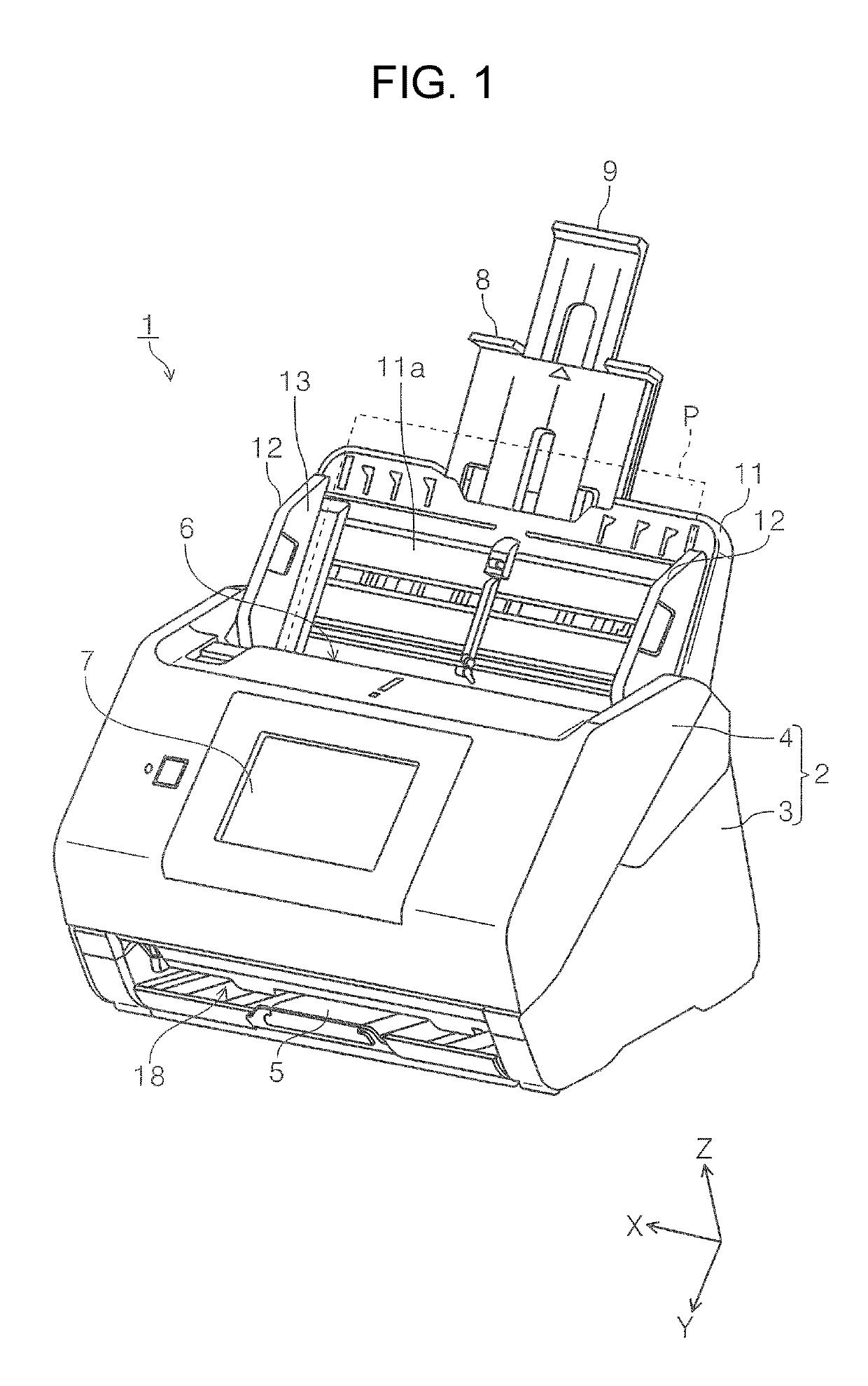
[0038]First, the outline of an image reading apparatus according to a practice example 1 of the invention will be described. In the present practice example, as one example of the image reading apparatus, a document scanner (hereinafter referred to as just a scanner 1) capable of reading at least one of the obverse side and the reverse side of a medium will be exemplified.

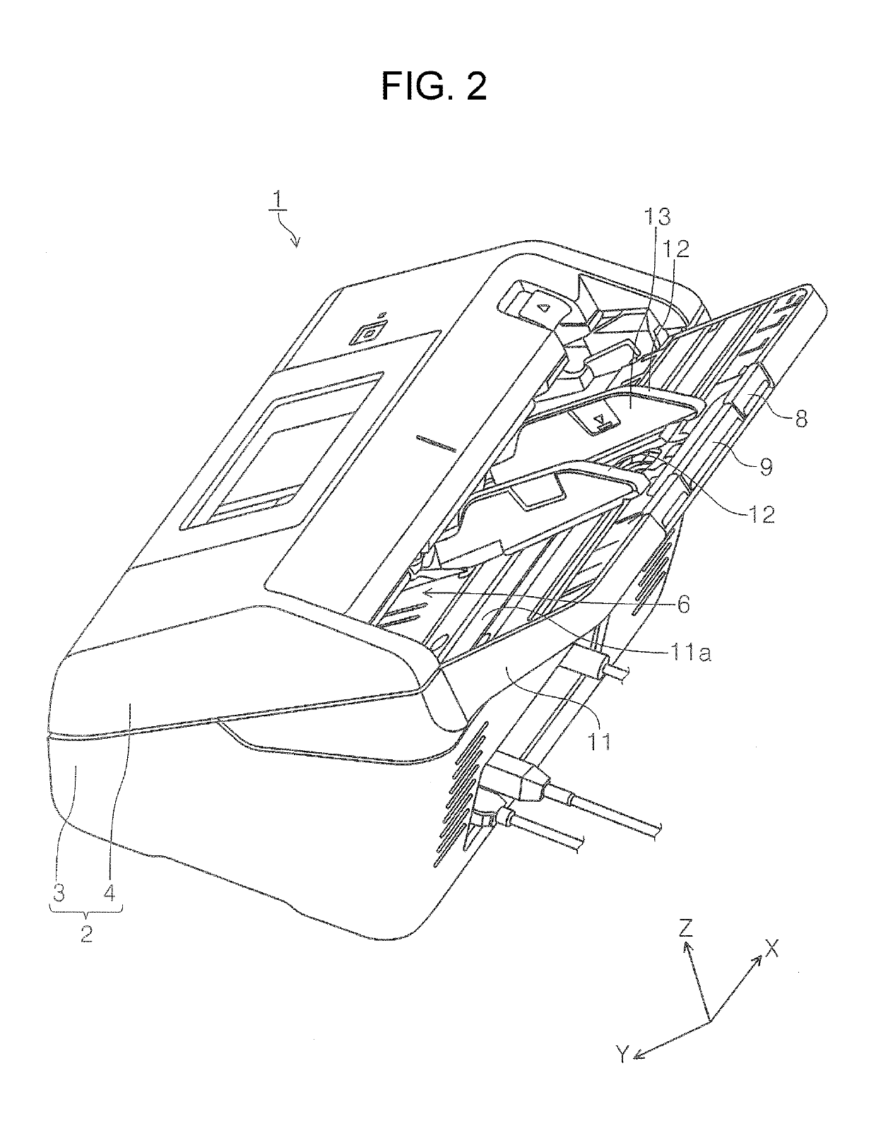
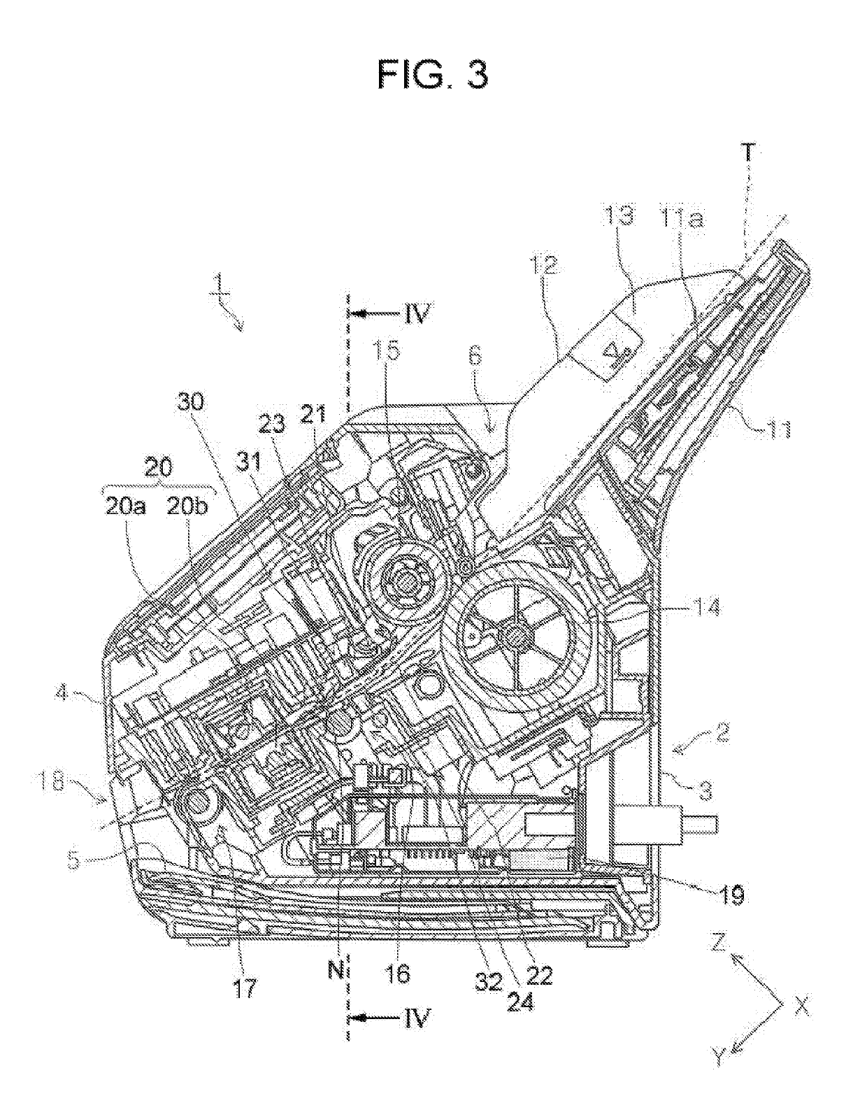
[0039]FIG. 1 is a perspective, exterior view of the scanner 1 according to the present practice example of the invention. FIG. 2 is a perspective view of the scanner 1 according to the present practice example of the invention, from an angle different from that of FIG. 1. FIG. 3 is a side cross-sectional view of the scanner 1 according to the present practice example of the invention, illustrating a paper transport path in the scanner 1. FIG. 4 is a cross-sectional view of the scanner 1, taken along the line IV-IV of FIG. 3. FIG. 5 is a diagram illustrating relations between output values from a r...

example 2

Practice Example 2

[0084]In this practice example 2, the configuration in the vicinity of the receiving portion 32 will be described with reference to FIG. 10. FIG. 10 is a cross-sectional view of the vicinity of the receiving portion 32 according to practice example 2, taken along the Y-Z plane. Note that, in the present practice example, the same components as the components of practice example 1 will be denoted by the same reference signs as those of the components of practice example 1, and thereby will be omitted from description.

[0085]In the present practice example, a shutter portion 40 (FIG. 10) is provided in the opening 25 of the lower concave portion 24 in which the receiving portion 32 is disposed. The shutter portion 40 is capable of adjusting an open state of the opening 25 of the lower concave portion 24 in such a way as to slide from the downstream side toward the upstream side in the medium transport direction. The shutter portion 40 is configured to be capable of sl...


PUM


Abstract

An image reading apparatus includes a feed roller configured to feed paper toward a reading section, and a medium detection section provided along a transport path between the feed roller and the reading section and configured to include a transmitting portion configured to output an output value equivalent to a magnitude of an ultrasonic wave, and determines whether the transport of the paper is to be continued or to be brought to a halt on the basis of a lower limit value and an upper limit value for the output value, which are set in accordance with the kind of the paper. Further, in a case where the output value satisfies a first condition, a transport of the medium is continued, and in a case where the output value satisfies a condition different from the first condition, the transport of the medium is brought to a halt.

Description

BACKGROUND1. Technical Field[0001]The present invention relates to image reading apparatuses for reading an image on each of documents while sequentially transporting the each document.2. Related Art[0002]Among scanners as an example type of image reading apparatuses, there are scanners mounting therein an ultrasonic wave sensor for the purpose of detecting multi-feeding with respect to a document (medium) that is read in a reading section. Such an ultrasonic wave sensor is configured to include a transmitting portion that is provided on one side of upper and lower sides of a medium being transported on a medium transport path and that is configured to emit an ultrasonic wave, and a receiving portion that is provided on the other side of the upper and lower sides and that is configured to receive the ultrasonic wave having been emitted from the transmitting portion (see, for example, Japanese Patent No. 5,331,568, Japanese Patent No. 5,404,870, and JP-A-2011-031999)[0003]Here, in a ...

Claims


Application Information

Patent Timeline
Patent Type & Authority Patents(United States)
IPC IPC(8): B65H7/12B65H3/52B65H3/06B65H7/14B65H7/06
CPCB65H7/14B65H3/5284B65H3/0653B65H3/063B65H7/125B65H7/06B65H2553/80B65H2220/03B65H2511/522B65H2553/30B65H2511/524H04N1/0057H04N1/00795H04N1/00814H04N1/04
Inventor KADOTA, SHUICHI
Owner SEIKO EPSON CORP
Why Eureka
Try Eureka