Polymeric Material For Use In And With Sterilizable Medical Devices

a technology of polymeric materials and medical devices, applied in the direction of mechanical control devices, instruments, applications, etc., can solve the problems of high tooling costs, high manufacturing costs in terms of the cost and amount of metal used, high tooling costs, etc., and achieve the effect of reducing or eliminating the occurrence of undesirable molding characteristics

Active Publication Date: 2016-08-04
KARL STORZ IMAGING INC
View PDF0 Cites 0 Cited by
  • Summary
  • Abstract
  • Description
  • Claims
  • Application Information

AI Technical Summary

Benefits of technology

[0011]One aspect of the invention is that the step of spin-welding the second plastic blank to the first plastic blank creates a shear welded joint having a shutoff path that traps flash, thereby preventing it from tarnishing the outer cosmetic surface of the knob assembly.
[0014]One aspect of the invention is that in each embodiment, undesirable molding characteristics (e.g. flow lines, knit lines, burn marks, and splay) are located on the sprues, center webs and “sacrificial” portions of the plastic material where gating connections are made during the plastic injection molding process, and these structures are completely removed by secondary machining or post machining during subsequent steps of manufacturing method. This minimizes or eliminates the occurrence of undesirable molding characteristics on the outer cosmetic surfaces of the knob assemblies.
[0015]Preferably, the plastic material used in the manufacturing of the knob assemblies of the invention comprises 99-100% polyphenylsulfone resin, 0.1-1% mica, 0.01-0.1% titanium dioxide, up to 0.01% tin oxide, 0.01-0.1% solvent blue 104, and 0.01-0.1% solvent violet 13. This unique plastic material gives the knob assemblies a metallic color to mimic and match the appearance of anodized metallic knobs, is capable of withstanding sterilization without showing any signs of degrading or fading of color, and it is versatile enough to be used in the manufacturing of various different medical device components, such as zoom knob assemblies, focus knob assemblies, and camera head sleeves. This is yet another aspect of the present invention.

Problems solved by technology

The design and method of manufacturing these prior art external adjuster assemblies unavoidably results in high manufacturing costs in terms of the cost and amount of the metal used, machining time, anodizing costs, assembly time, and inspection time.
Also, using this manufacturing method, it is difficult, if not impossible, to machine the external adjuster assemblies with consistent precision.
One disadvantage of MIM processes is that they can require the application of several hundred tons of pressure to a mold, which results in high tooling costs.
Additionally, the metal blanks that are used in the MIM processes are expensive and usually require a significant amount of “secondary machining” or “post machining” to achieve the desired high-precision dimensions of the final components.
This manufacturing method therefore results in extremely high manufacturing costs for manufacturing external adjuster assemblies.
However, one problem with plastic injection molding processes is that they may leave undesirable molding characteristics on the outer cosmetic surfaces of the final product, such as visible flow marks, weld lines, knit lines, gate marks, sink marks, and ejection pin marks.
Additionally, during the assembly of plastic components, an undesired layer of material, also known as “flash,” may escape to the outer cosmetic surfaces of the final product, and flash removal may be costly.
Further, the cosmetic appearance of plastic components is typically not as visually appealing as metallic components, and polymeric components may have the tendency to degrade under high temperature steam autoclave sterilization.

Method used


Image

  • Polymeric Material For Use In And With Sterilizable Medical Devices
  • Polymeric Material For Use In And With Sterilizable Medical Devices
  • Polymeric Material For Use In And With Sterilizable Medical Devices

Examples


Embodiment Construction

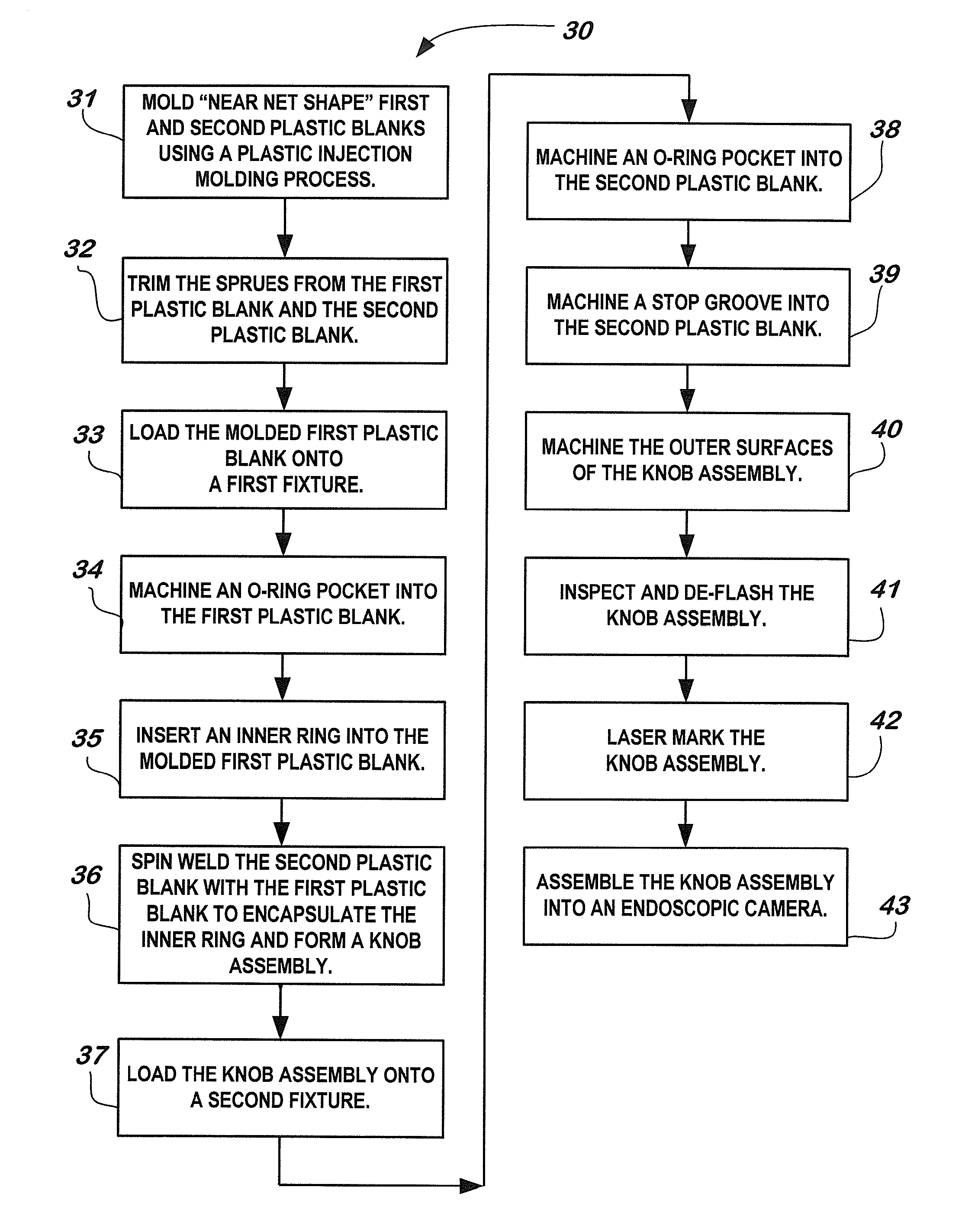
[0030]The present invention provides a method of manufacturing an endoscopic video camera having one or more external adjuster assemblies, such as a zoom knob assembly or a focus knob assembly.

[0031]FIG. 3. illustrates various steps of the manufacturing method 30 in accordance with the first embodiment of the present invention. Manufacturing method 30 utilizes a near net machining concept. Under this concept, a plastic or metal blank, which includes all molding features (e.g. gating system, sprue) is first molded by a plastic injection molding (IM) process or a metal injection molding (MIM) process to a “near net shape” of the final component such that minimal secondary machining is required to meet the specification of, for example, a final component such as a plastic zoom knob or a metallic inner ring for an endoscopic video camera.

[0032]The term “IM process” refers to the process which uses plastic material, a hollow mold, and an injection molding machine to manufacture plastic c...


PUM

PropertyMeasurementUnit
vertical displacementaaaaaaaaaa
diameteraaaaaaaaaa
temperatureaaaaaaaaaa

Abstract

The invention provides an endoscopic video camera having a polymeric knob assembly, wherein the polymeric material used for manufacturing the knob assembly includes polyphenylsulfone resin, titanium dioxide, tin oxide, and colored metallic additives, is capable of withstanding sterilization, and has a metallic cosmetic appearance. The invention also provides methods of manufacturing the knob assembly by plastic injection molding processes, wherein undesirable molding characteristics are concentrated on portions of the knob assembly that are removed by secondary machining or post machining.

Description

FIELD OF THE INVENTION[0001]The present invention is generally related to a method of manufacturing medical device components, more particularly, to a method of manufacturing medical grade polymeric knob assemblies for use in endoscopic video cameras.BACKGROUND OF THE INVENTION[0002]Endoscopes and endoscopic video cameras are now widely used by physicians during surgery to view inside body cavities. Typically, the endoscopic video camera contains an optical focusing lens, an optical zoom lens, and a focus and zoom device that can be adjusted to optimize images transmitted by the endoscope. After each use with a patient, the endoscope and endoscopic video camera must be cleaned and sterilized before they can be used again. Due to cost and time considerations, it is desirable to sterilize both endoscopes and endoscopic video cameras using high temperature steam autoclaving.[0003]The focus and zoom device usually includes external adjuster assemblies (e.g. a focusing knob assembly and ...

Claims


Application Information

Patent Timeline
Patent Type & Authority Applications(United States)
IPC IPC(8): A61B1/00G05G1/10B22F7/04A61B1/045C08K3/34C08K3/22A61L31/06B29D15/00G05G5/04
CPCA61B1/0011C08K2003/2231G05G1/10B22F7/04G05G5/04C08K3/34C08K3/22A61L31/06A61B1/00066A61B1/00105A61B1/00142A61B1/045B22F2007/042B29K2081/06B29K2105/16B29K2505/08B29K2505/06B29K2509/10B29K2995/0021C08K2003/2241B29D15/00B22F3/225B22F5/106B22F7/06C08K3/346C08K5/0041C08K5/18C08K2201/014C08L81/06A61L31/022A61L31/028A61B90/08A61B90/361A61B2090/0813B29K2509/08G02B23/2476
Inventor KWAN, KIN MINGKORKUT, DEJANANHALT, THOMAS J.MCCARTY, PAUL
Owner KARL STORZ IMAGING INC
Why Eureka
Try Eureka