Low-profile monopulse tracker

a tracker and low-profile technology, applied in the direction of instruments, measurement devices, antennas, etc., can solve problems such as undesirable configurations

Active Publication Date: 2019-11-19
L3 TECH INC
View PDF16 Cites 6 Cited by
  • Summary
  • Abstract
  • Description
  • Claims
  • Application Information

AI Technical Summary

Benefits of technology

[0007]Each of the monopulse antenna systems can independently generate three tracking channels (Σ, Δaz, and Δel) which can then be employed to generate ratios representing the azimuth and elevation angles of the object relative to the boresight axis of the respective monopulse antenna system. Because of the orientations of the monopulse antenna systems, a tracked object (e.g, a projectile) will likely be within the field of view of multiple monopulse antenna systems such that, at any given time, multiple monopulse antenna systems will generate ratios representing the azimuth and elevation angles

Problems solved by technology

However, such configurations may be undesirable in many situations such as on aircraft where a pedestal-mount

Method used


Image

  • Low-profile monopulse tracker
  • Low-profile monopulse tracker
  • Low-profile monopulse tracker

Examples


Embodiment Construction

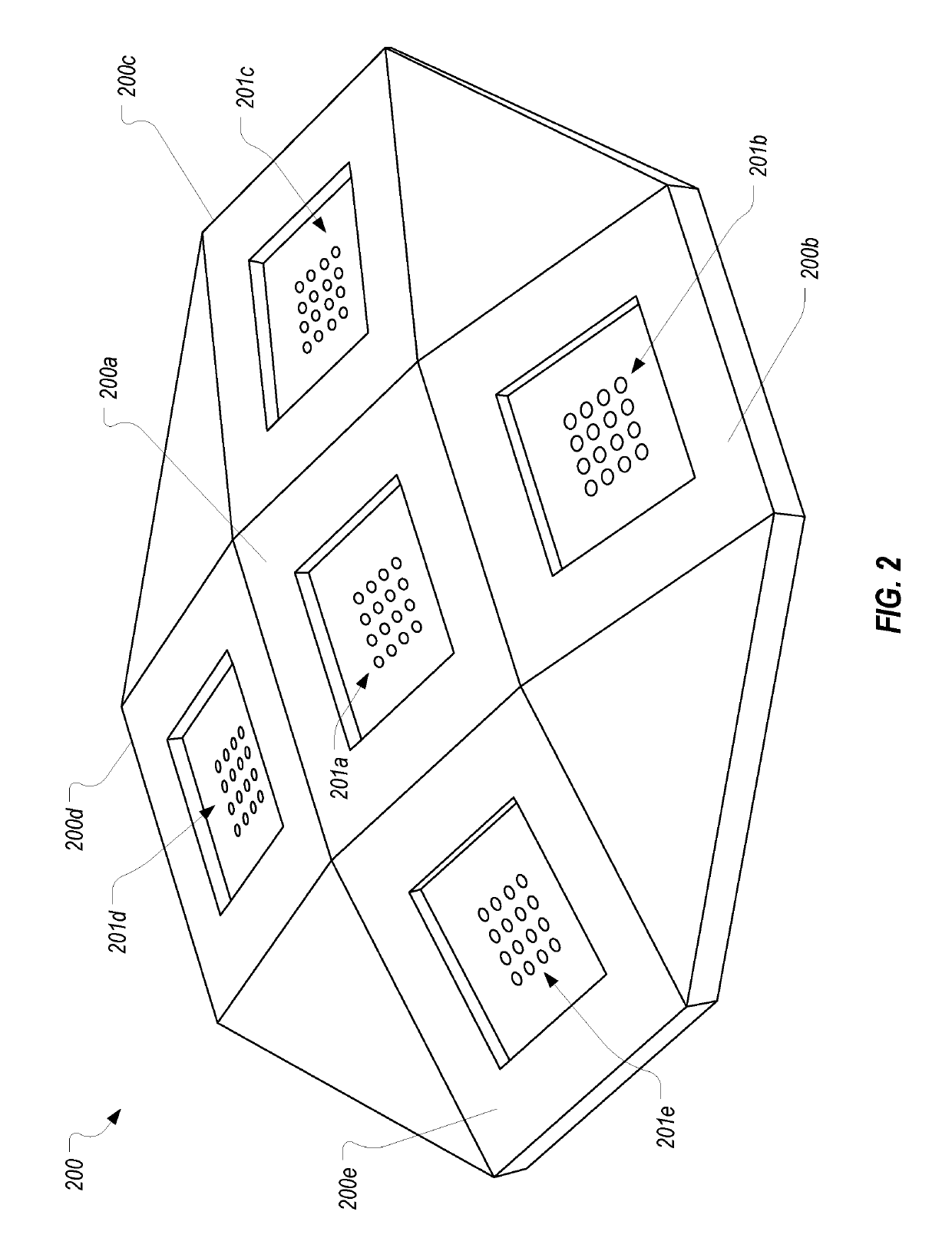
[0024]FIG. 2 illustrates an example of a low-profile monopulse tracker 200 that is configured in accordance with one or more embodiments of the present invention. As shown, monopulse tracker 200 can comprise a housing having a pyramid shape forming a top surface 200a and four side surfaces 200b-200e that are each angled relative to top surface 200a. Top surface 200a extends in a plane having a first and second axis as identified in FIG. 2B. Side surfaces 200b and 200d are positioned on opposite sides of top surface 200a and are aligned with top surface 200a along the first axis. Similarly, side surfaces 200c and 200e are positioned on opposite sides of top surface 200a but are aligned with top surface 200a along the second axis.

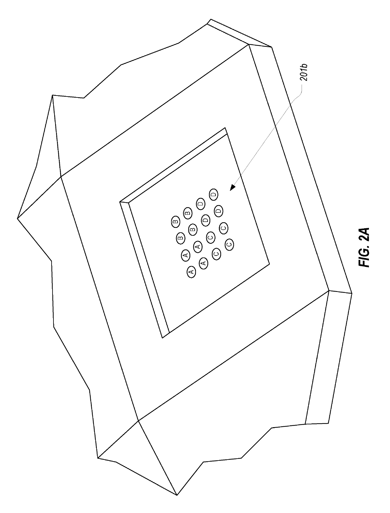
[0025]Each of surfaces 200a-200e includes a monopulse antenna system 201a-201e respectively. Each monopulse antenna system 201a-201e can preferably be a planar dual-axis monopulse antenna system. As is known in the art, any multiple of four antenna elements m...


PUM


Abstract

A monopulse tracker includes multiple dual-axis monopulse antenna systems that are angled with respect to one another. The orientations of the monopulse antenna systems create a much larger field of view for the monopulse tracker to eliminate the need to steer the monopulse tracker. The monopulse tracker can be configured to estimate a position of an object based on tracking information received from more than one monopulse antenna system therefore increasing the accuracy of the estimated position. The multiple monopulse antenna systems can be arranged in a low-profile housing to facilitate use of the monopulse tracker on aircraft.

Description

CROSS-REFERENCE TO RELATED APPLICATIONS[0001]N / ABACKGROUND[0002]A monopulse antenna system is commonly used to implement radar tracking. As its name implies, for a radar application a monopulse antenna system employs a single pulse to identify the presence of an object in the field of view. This is possible due to the use of multiple antenna elements which can detect angle information from the received signal. A monopulse antenna system can also be used to track intentional radiators.[0003]FIG. 1 illustrates an example block diagram of a typical dual-axis monopulse antenna system. As shown, a dual-axis monopulse antenna system may include four antenna elements (A, B, C, and D) each of which receive the same signal. If an object is in the field of view of the monopulse antenna system, each antenna element will receive the reflected signal. These received signals (which are referred to as A, B, C, and D respectively) are then fed to a comparator network.[0004]Due primarily to the slig...

Claims


Application Information

Patent Timeline
IPC IPC(8): G01S13/68G01S13/44
CPCG01S13/44G01S13/68G01S7/023G01S7/4026G01S13/726G01S7/0232G01S7/0235G01S7/403G01S7/4034H01Q25/02
Inventor HOLLENBECK, MICHAEL CPRESTWICH, SYBENCH, JEFFREY B
Owner L3 TECH INC
Why Eureka
Try Eureka