
Centrifuge rotor mounted on drive shaft

Active Publication Date: 2019-11-26
ANDREAS HETTICH GMBH & CO KG
View PDF66 Cites 2 Cited by
  • Summary
  • Abstract
  • Description
  • Claims
  • Application Information

AI Technical Summary

Benefits of technology

The invention solves the problem of a centrifuge rotor not being securely locked to the lid in the handle. By adding a blocking body to the rotor and engaging it with a support, the rotor is securely locked and positioned relative to the drive shaft. This improves the safety of the centrifuge and reduces the need for major constructional efforts.

Problems solved by technology

However, practice has shown that especially with solutions of the type which enable particularly simple unlocking of the lid, there is the inherent risk of the locking device being released unintentionally.
If the locking device is inadvertently deactivated in transport, the rotor will become detached from the rotor and fall to the ground.
Nonetheless, even in this configuration, the pushbutton may still be pressed by accident, thus causing the lid to become detached from the rotor carried by means of the handle.

Method used


Image

  • Centrifuge rotor mounted on drive shaft
  • Centrifuge rotor mounted on drive shaft
  • Centrifuge rotor mounted on drive shaft

Examples


Embodiment Construction

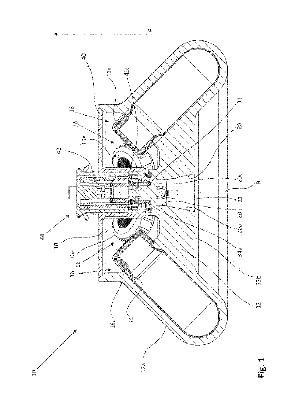
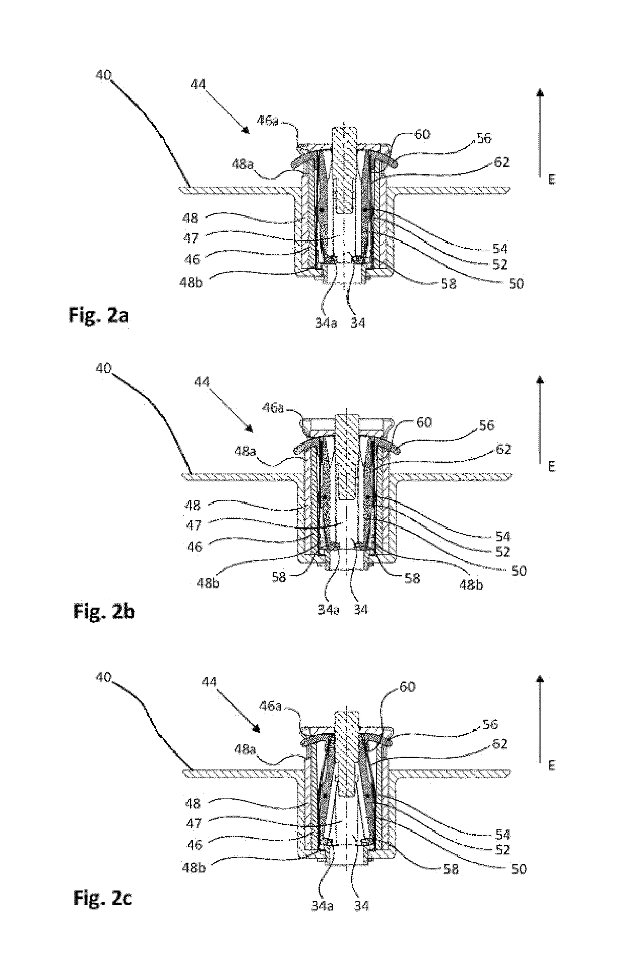
[0046]FIG. 1 is a lateral sectional view of a rotor 10 according to the invention with the lid 40 in place and activated locking of the lid 40.

[0047]The rotor 10 has the basic shape of a truncated cone which tapers toward the top. Provided in a rotor head 12 in a conventional manner and uniformly spaced from each other are receiving units 14 for sample containers 16. The longitudinal extension of the receiving units 14 is parallel to the lateral surface 12a of the rotor head 12. The view of FIG. 1 shows four sample containers 16 inserted in the receiving units 14. Sealing caps 16a of the sample containers 16 protrude from the respective receiving units 14 into a receiving chamber 18 of the rotor 10.

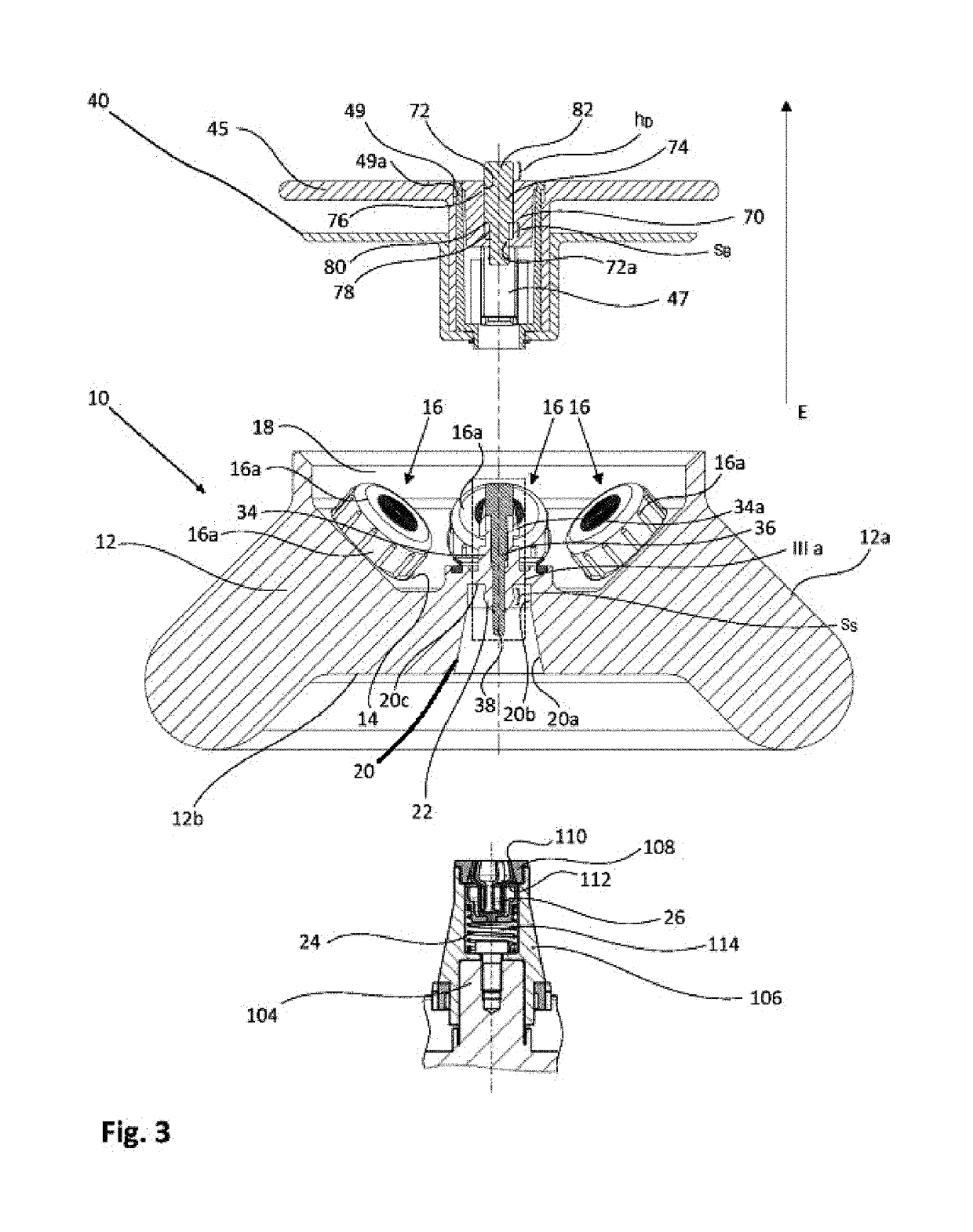
[0048]Mounted concentrically in a bottom 12b of the rotor head 12 is a rotor seat 20 which is associated with the support 106 of the centrifuge 100. The rotor seat 20 has a frusto-conical first portion 20a which tapers in a removal direction E and which is adjoined in an axial direction b...


PUM


Abstract

A rotor 10 of a centrifuge 100, having a receiving chamber 18 for samples to be centrifuged, a concentrically mounted seat 20 which is associated with a support 106 of a drive shaft 104 of said centrifuge 100, a lid 40 which limits the receiving chamber 18 at the top, which is mounted concentrically relative to the rotor and which has, on its side remote from the receiving chamber 18, a handle 44 for carrying the rotor and the lid 40, and a locking mechanism 50, 34b of lid 40 and rotor, which locking mechanism 50, 34b comprises a locking element 50 which can be moved between a locking position and an unlocking position thereof. In accordance with the invention, part of the handle 44 is adapted to be movable and is operatively connected to a retaining element 48b, 48c, which retaining element 48b, 48c can be moved, by the handle 44, between a first position which prevents actuation of the locking element 50, and a second position which releases the locking element 50.

Description

[0001]This patent application claims priority to German patent application no. DE 10 2015 113 855.7, filed Aug. 20, 2015. German patent application no. DE 10 2015 113 855.7, filed Aug. 20, 2015, is incorporated herein by reference hereto in its entirety.[0002]The invention relates to a rotor of a centrifuge as well as to a centrifuge with a rotor of this type.BACKGROUND OF THE INVENTION[0003]A multitude of rotors for centrifuges are known from the prior art which each have a receiving chamber that can be sealed with a lid. This protects the centrifuge and the environment from contamination in the event of a vessel rupture.[0004]Operation safety will be increased if a mechanism is provided which locks the closure of the lid. For example, the closure can include a latching element which has an activating element provided on the top of the lid, for example a pushbutton. The latching element may furthermore be spring-loaded in a locking direction thereof so that it will automatically la...

Claims


Application Information

Patent Timeline
IPC IPC(8): B04B7/06B04B9/08B04B7/02
CPCB04B7/06B04B9/08B04B2007/025B04B2009/085B04B5/0407B04B7/02B04B5/0414B04B7/08
Inventor HORNEK, MATTHIASPRILLA, RAINERHOELDERLE, ANDREASEBERLE, KLAUS-GUENTER
Owner ANDREAS HETTICH GMBH & CO KG
Learn More