Support structure for an optical fiber cable

a technology of optical fiber cable and support structure, which is applied in the field of communication cables, can solve the problems of high installation effort of optical fiber cables

Active Publication Date: 2019-11-26
ING3 BET GMBH
View PDF7 Cites 0 Cited by
  • Summary
  • Abstract
  • Description
  • Claims
  • Application Information

AI Technical Summary

Benefits of technology

[0007]In view of the foregoing background, it is therefore an object of the present invention to provide a support structure for an optical fiber cable that may be easily handled and installed in an aerial configuration.

Problems solved by technology

A common problem of all cable types is the high effort for their installation, which rises with the number of access closures.

Method used


Image

  • Support structure for an optical fiber cable
  • Support structure for an optical fiber cable
  • Support structure for an optical fiber cable

Examples


Embodiment Construction

[0022]The invention will now be described more detailed h reference to the accompanying drawings, in which preferred embodiments of the invention are shown. However, the invention may be embodied in many different forms and is not limited to the embodiment set forth herein.

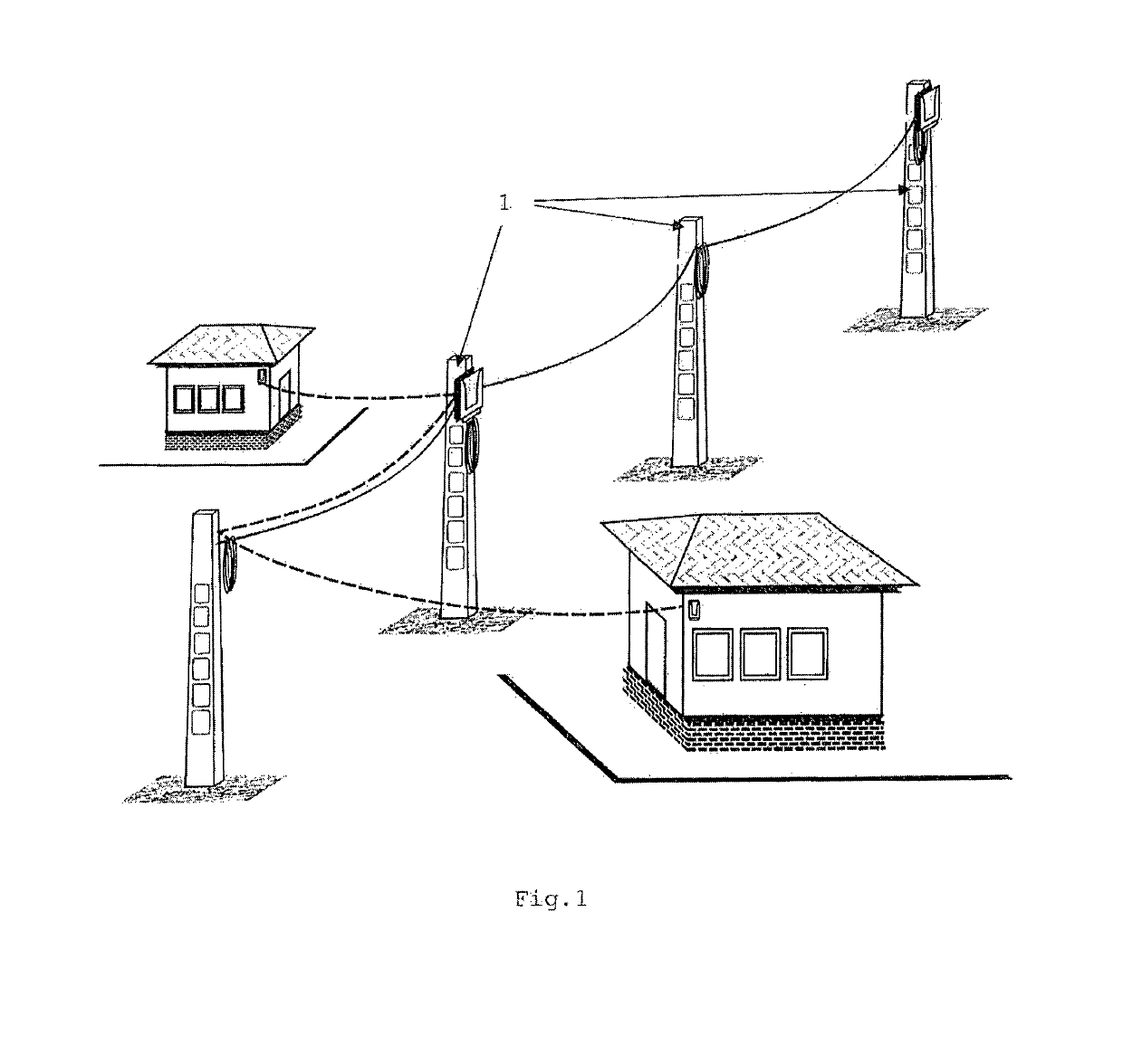
[0023]As shown in FIG. 1, the inventive sup ort structure is tended to be used in the aerial part f an optical fiber communication network.

[0024]In such a network, a fiber optic cable 7 has to be aerially installed along a series of vertical supports or poles 1.

[0025]It has to resist the forces of nature, in particular the loads of wind or ice.

[0026]Self-supporting aerial cables, which meet these demands are relatively stiff and difficult to handle during installation.

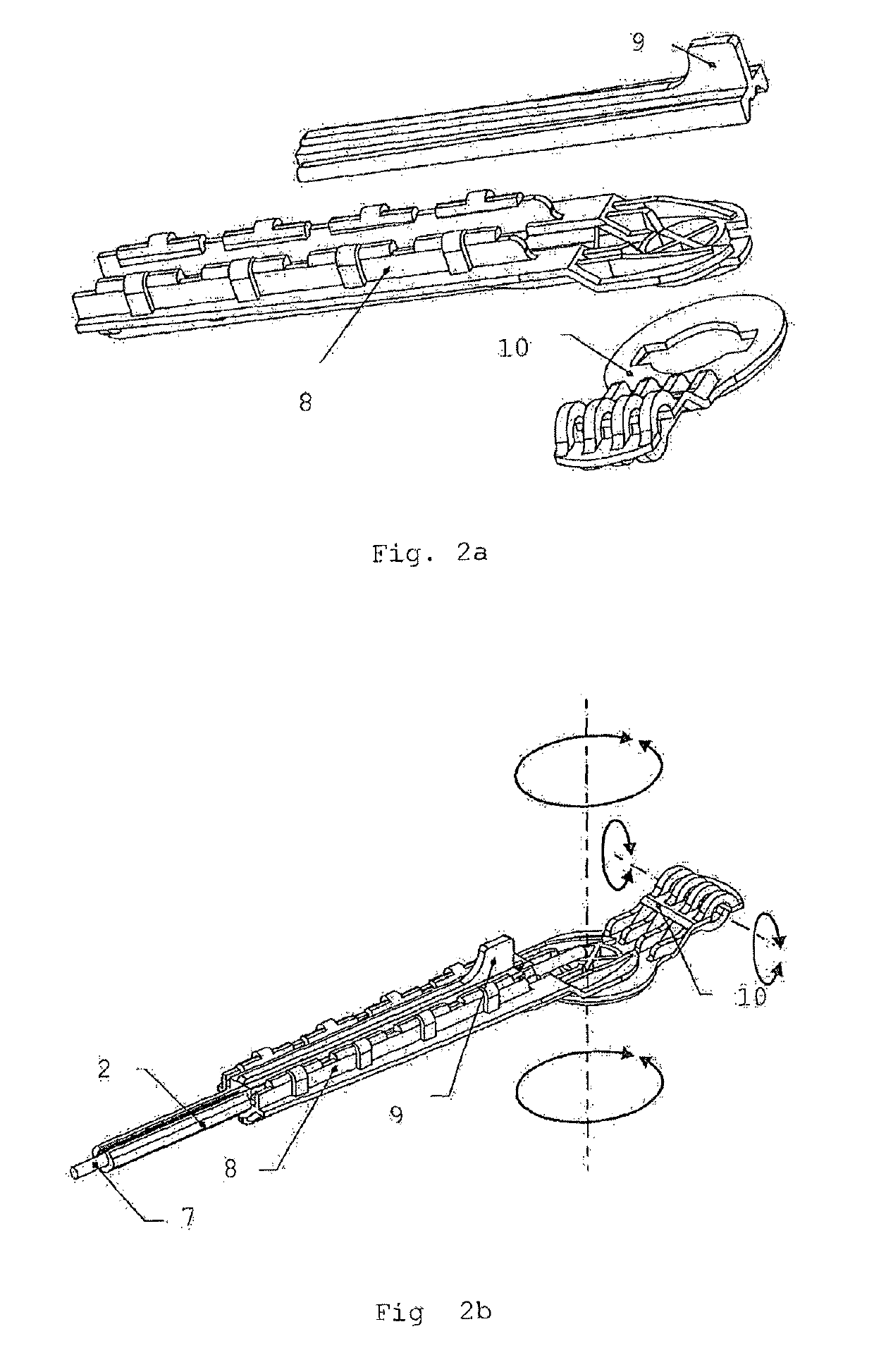
[0027]According to the invention, this problem can be solved by using a support structure, which gives the optical fiber cable the required strength, brat simplifies the handling.

[0028]The support structure is secured to the end poles of the aerial n...


PUM


Abstract

The invention relates to a support structure for an optical fiber cable (7) adapted to be aerially installed in a configuration, extending generally horizontally along a series of spaced apart vertical pilots, said support structure comprising: —An approximately c-shaped support element (2) with an open hollow (3), prepared for the incorporation of an optical fiber cable (7); —at least one longitudinal strength member (6) integrated in the c-shaped support element (2); —wherein the optical fiber cable (7) is movable arranged in the hollow (3) of the support element (2).

Description

CROSS-REFERENCE TO RELATED APPLICATIONS[0001]This is a 35 U.S.C. 371 National Stage Patent Application of International Application No. PCT / EP2017 / 000266, filed Feb. 27, 2017, which claims priority to European application 16000504.7, filed Mar. 2, 2016, each of which is hereby incorporated by reference in its entirety.FIELD OF THE INVENTION[0002]The invention relates to the field of communication cables, and, more particularly, to a support structure for an aerial optical fiber cable.BACKGROUND OF THE INVENTION[0003]Communication cables employing optical fibers are widely used in the telecommunications industry. In particular, multifiber cables are widely used for long distance telephone communications, interexchange telephone applications, and other telephony and data transmission applications. Fiber optic cables are also being incorporated into cable television networks in place of more traditional coaxial cables. Optical fibers may permit long distances between signal repeaters o...

Claims


Application Information

Patent Timeline
Patent Type & Authority Patents(United States)
IPC IPC(8): G02B6/44G02B6/48H02G7/05
CPCG02B6/4433G02B6/4435G02B6/4471G02B6/483H02G7/053
Inventor KATÓ, IMRE
Owner ING3 BET GMBH
Why Eureka
Try Eureka