Implement with forward folding wing frames

a technology of forward folding and wing frame, which is applied in the field of agricultural implements, can solve the problems of difficult to move under utility lines, bridges, and difficulty in towing stability, and achieve the effect of simple actuator control

Active Publication Date: 2019-12-10
PILLAR LASERS
View PDF19 Cites 0 Cited by
  • Summary
  • Abstract
  • Description
  • Claims
  • Application Information

AI Technical Summary

Benefits of technology

[0013]The present disclosure provides a wide forward folding implement where no complex and costly telescoping mechanism is required. All wheels are castering wheels, facilitating movement between the operating and transport positions, and the pivoting movement of the wheels about the respective caster axes is controlled to provide a desired operating castering action when the tool bar frame is in the operating position, and a different desired transport castering action when the tool bar frame is in the transport position. The castering action is controlled conveniently by hydraulic cylinders, electric actuators, or like devices which may be operated manually or remotely from the towing vehicle. The required control of the actuators is simple, as the actuators are either in a lock / catch mode or a release mode.

Problems solved by technology

It is common to fold the wing frames upward and inward to a more compact transport position as disclosed in U.S. Pat. No. 6,684,962 to Lewallen, however with wider implements the implement in the transport position can be quite high causing stability problems as well as making same difficult to move under utility lines, bridges, and the like.
These carts can be very large and must be towed rearward of ends of the wing frames in the transport position which is a significant distance from the towing tractor such that stability during towing can be problematic.
It is also known to fold the wing frames of agricultural implements forward to a more compact transport position however the width of the implement is limited by the length of the hitch.
Such telescoping hitches require considerable added material to provide the required strength to resist the forces exerted on the hitch, and lock mechanisms are required to secure the hitch in the extended and retracted positions which must be engaged and disengaged when moving between the operating and transport positions, adding time and complexity.
This telescoping also adds complexity when locating hydraulic lines from the tractor to the implement, product lines for air seeders, and the like.

Method used


Image

  • Implement with forward folding wing frames
  • Implement with forward folding wing frames
  • Implement with forward folding wing frames

Examples


Embodiment Construction

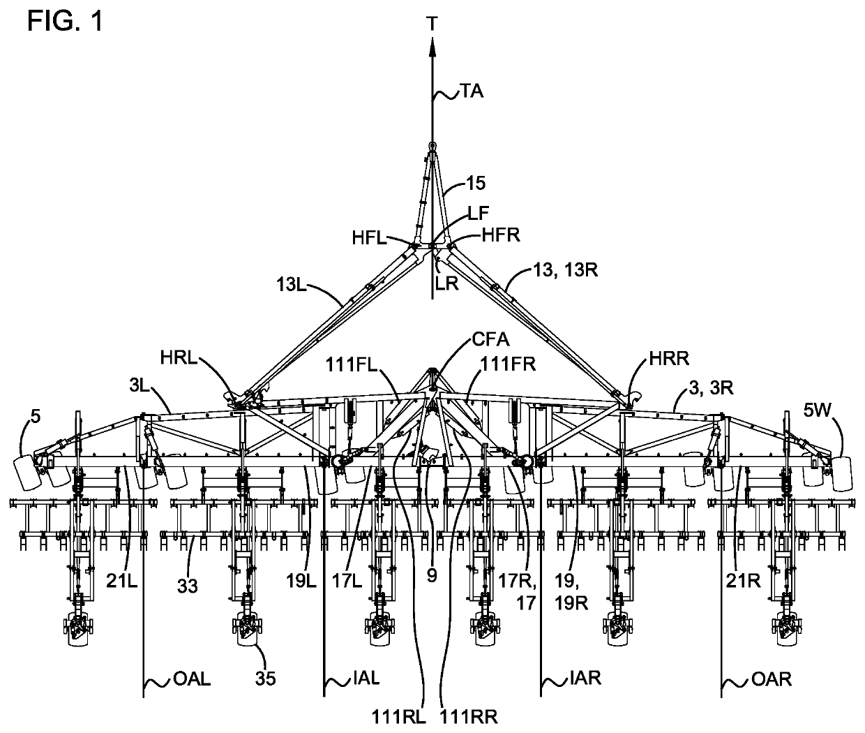
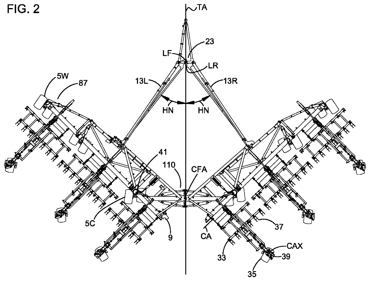
[0032]FIGS. 1-4 and 7 illustrate an embodiment of an implement apparatus 1 of the present disclosure. The apparatus 1 comprises a tool bar frame 3 mounted on tool bar wheels 5 for travel along a ground surface 7 in an operating travel direction T. The tool bar frame 3 comprises a right tool bar frame 3R and a left tool bar frame 3L pivotally attached at a front inner end thereof to a front inner end of the right tool bar frame 3R about a vertical center frame axis CFA located on a central tool bar axis TA that is aligned with the operating travel direction in a center of the tool bar frame 3.

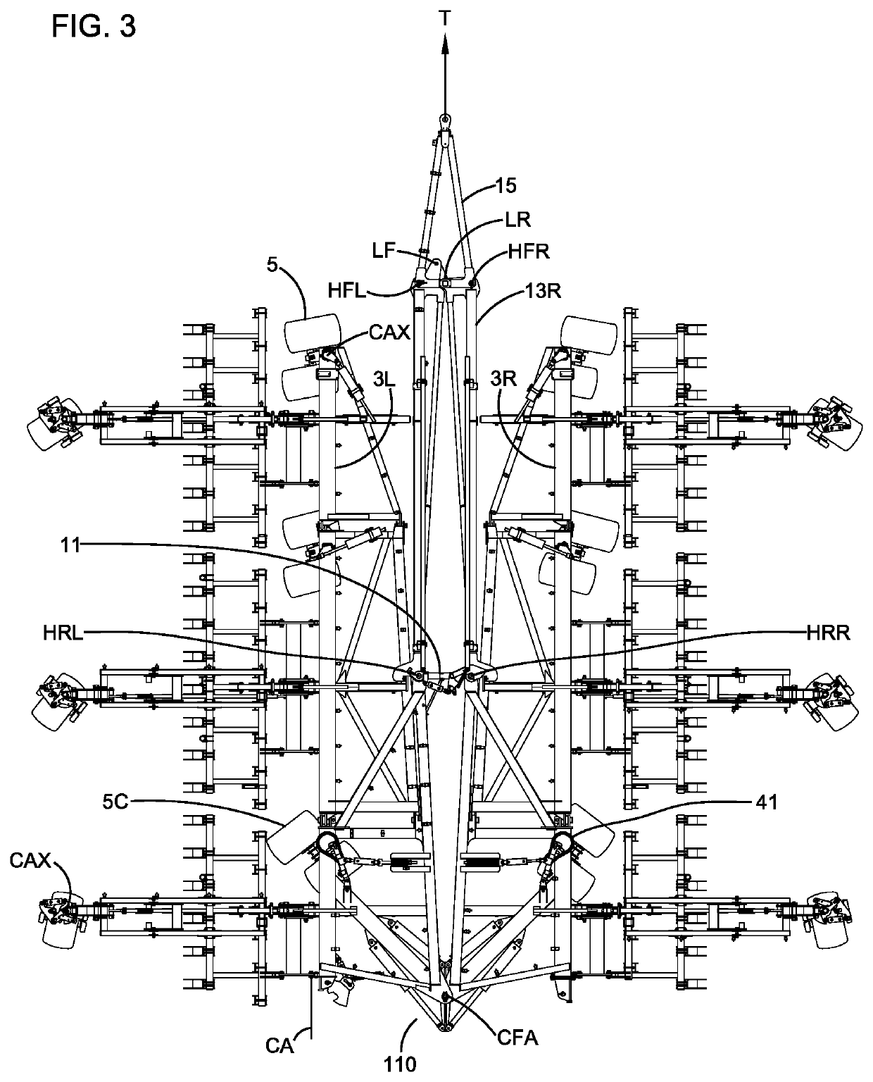
[0033]The tool bar frame 3 is movable from an operating position shown in FIG. 1, where the right and left tool bar frames 3R, 3L are oriented substantially perpendicular to the central tool bar axis TA and extend laterally away from the central tool bar axis TA, to a transport position shown in FIGS. 3 and 4 where the right and left tool bar frames 3R, 3L are substantially aligned with the cent...


PUM


Abstract

An implement has right and left pivotally attached tool bar frames movable from an operating position extending laterally to a transport position extending forward from the connecting pivot axis. Right and left hitch arms are pivotally attached about vertical axes at rear ends to spaced apart locations the right and left tool bar frames and extend forward and inward when the tool bar frame is in the operating position. A hitch frame is pivotally attached at right and left rear portions thereof to front ends of the hitch arms about vertical axes. When the tool bar frame is in the transport position, the rear end of the hitch frame is forward of the right and left tool bar frames, and the front end of the hitch frame, attachable to a tractor, is a desired clearance distance forward of the right and left tool bar frames.

Description

CROSS-REFERENCE TO RELATED APPLICATION[0001]This application claims priority to and benefit of CA Serial No. 2,964,431, filed Apr. 18, 2017, the contents of which are incorporated by reference in their entirety for all purposes.FIELD OF THE INVENTION[0002]This disclosure relates to the field of agricultural implements and in particular an implement with forward folding wing frames.BACKGROUND[0003]Wide agricultural implements typically include wing frames extending laterally from a center of the implement where each wing frame is pivotally attached to the adjacent wing frame about a horizontal pivot axis aligned with the operating travel direction such that each wing frame can pivot up and down with respect to the next to follow ground contours and maintain a desired depth of ground penetration of ground engaging tools such as furrow openers.[0004]It is common to fold the wing frames upward and inward to a more compact transport position as disclosed in U.S. Pat. No. 6,684,962 to Lew...

Claims


Application Information

Patent Timeline
Patent Type & Authority Patents(United States)
IPC IPC(8): A01B73/06
CPCA01B73/065A01B73/005
Inventor FRIGGSTAD, TERRANCE A.
Owner PILLAR LASERS
Why Eureka
Try Eureka