
Systems and methods for reducing switch stress in switched mode power supplies

a technology of switched mode power supply and switch stress, applied in the field of power electronics, can solve problems such as unsatisfactory effects, and achieve the effect of reducing the requirement for simultaneous control and reducing the number of shoot-through paths

Active Publication Date: 2018-11-27
MAXIM INTEGRATED PROD INC
View PDF3 Cites 0 Cited by
  • Summary
  • Abstract
  • Description
  • Claims
  • Application Information

AI Technical Summary

Benefits of technology

[0021]In another aspect, a system configured for operating point avoidance is provided, the system comprising: a digital pulse-width modulator; a critical duty cycle avoidance control logic unit for, upon detecting that a desired duty ratio value is near or equivalent to one or more critical duty ratio values, controlling the digital pulse-width modulator to operate an averaging sequence, the averaging sequence adapted to, on average, result in, or sufficiently approximate, the desired duty ratio, but not operate at the one or more critical duty ratio values such that the one or more critical operating points are avoided.
[0027]In another aspect, the averaging sequence provides for dead-time adjustment during the operation of the multi-level converter when then the target duty cycle value is equal or approximately equal to one or more critical duty ratio values, thereby reducing a requirement for simultaneous control and reducing a number of shoot-through paths.

Problems solved by technology

The operation of switched mode power supplies at particular operating points or at various operating characteristics may cause undesirable effects, including, for example, undesirable transient effects.

Method used


Image

  • Systems and methods for reducing switch stress in switched mode power supplies
  • Systems and methods for reducing switch stress in switched mode power supplies
  • Systems and methods for reducing switch stress in switched mode power supplies

Examples


example implementation

[0118]The following section describes some illustrative examples of implementation of the controller, various control systems, and / or control methods. The examples are meant to be illustrative and non-limiting. Other variations having more, less, and / or different components and / or configurations may be possible.

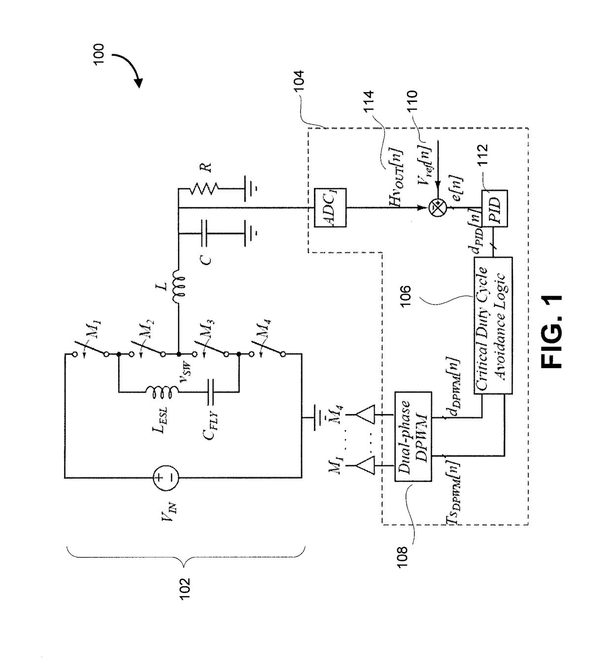
[0119]A possible embodiment of critical duty cycle avoidance control method is depicted with block diagrams in FIG. 1 and FIG. 6. FIG. 6 is an example block schematic illustrating a digital implementation of the critical duty cycle avoidance controller, according to some embodiments.

[0120]The controller (e.g., a digital controller) may, in some embodiments, be provided as a modification of a standard digital voltage-mode pulse width-modulated (PWM) controller, where a conventional digital pulse-width modulator (DPWM) is replaced with a two-phase DPWM, to accommodate 4-switch operation.

[0121]In some embodiments, a controller may be provided as a specially configured pulse widt...


PUM


Abstract

In various embodiments described in the present disclosure, various methods and systems are introduced, that may reduce and / or eliminate the voltage spikes on the power switches by avoiding operation at zero-ripple duty ratios. In a first aspect, a method for reducing voltage spikes across switches in a multi-level converter is provided, the method comprising: receiving an error value associated with a difference between a measured output voltage and a reference output voltage; determining a target duty cycle value based at least on a control feedback loop adapted to minimize the error value; if the target duty cycle value is equal or approximately equal to one or more critical duty ratio values, controlling the operation of the multi-level converter to operate the multi-level converter with an averaging sequence, the averaging sequence adapted to, on average, result in, or sufficiently approximate, the one or more critical duty ratio values, but not operate at the one or more critical duty ratio values; and generating one or more pulse-width modulated signals to control the operation of the multi-level converter based on at least one of the target duty cycle and the averaging sequence.

Description

FIELD[0001]The present disclosure generally relates to the field of power electronics and more specifically, the operation of switched mode power supplies.INTRODUCTION[0002]The operation of switched mode power supplies at particular operating points or at various operating characteristics may cause undesirable effects, including, for example, undesirable transient effects.SUMMARY[0003]In a first aspect, a method for reducing voltage spikes across switches in a multi-level converter is provided, the method comprising: measuring an output voltage of the multi-level converter; comparing the measured output voltage to a reference output voltage to process an error value associated with a difference between the measured output voltage and the reference output voltage; determining a target duty cycle value based at least on a control feedback loop mechanism adapted to minimize the error value; if the target duty cycle value is equal or approximately equal to one or more critical duty rati...

Claims


Application Information

Patent Timeline
Patent Type & Authority Patents(United States)
IPC IPC(8): H02M1/088H02M1/14H02M3/158H02M1/00
CPCH02M1/088H02M3/158H02M1/14H02M2001/0058H02M7/4837Y02B70/10H02M1/0058
Inventor VUKADINOVIC, NENADPRODIC, ALEKSANDARARNOLD, CORY BRENTMIWA, BRETT A.BAKER, MICHAEL WARREN
Owner MAXIM INTEGRATED PROD INC
Learn More