
Three-dimensional touch module and detection method thereof

a three-dimensional touch and detection method technology, applied in the field of three-dimensional touch modules and detection methods thereof, can solve the problems of reducing the measurement accuracy affecting the operation reducing the accuracy of the measurement of the touch position and pressure value, so as to reduce the configuration requirements of the control module, improve the response speed of the three-dimensional touch assembly, and detect the two signals more accurately

Active Publication Date: 2021-09-30
TPK TOUCH SOLUTIONS (XIAMEN) INC
View PDF6 Cites 0 Cited by
  • Summary
  • Abstract
  • Description
  • Claims
  • Application Information

AI Technical Summary

Benefits of technology

The present invention provides a three-dimensional touch module and its detection method with improved accuracy, reduced interference, and wider application scope. The module includes a two-dimensional input assembly and a pressure sensing assembly, which output separate signals through the same input points. The signals are analyzed by a control module to determine touch position and pressure value. The two signals are used simultaneously or in different time sequences to improve response speed and accuracy. This detection method reduces the cost of the control module and enables more control modules to be used with the three-dimensional touch assembly.

Problems solved by technology

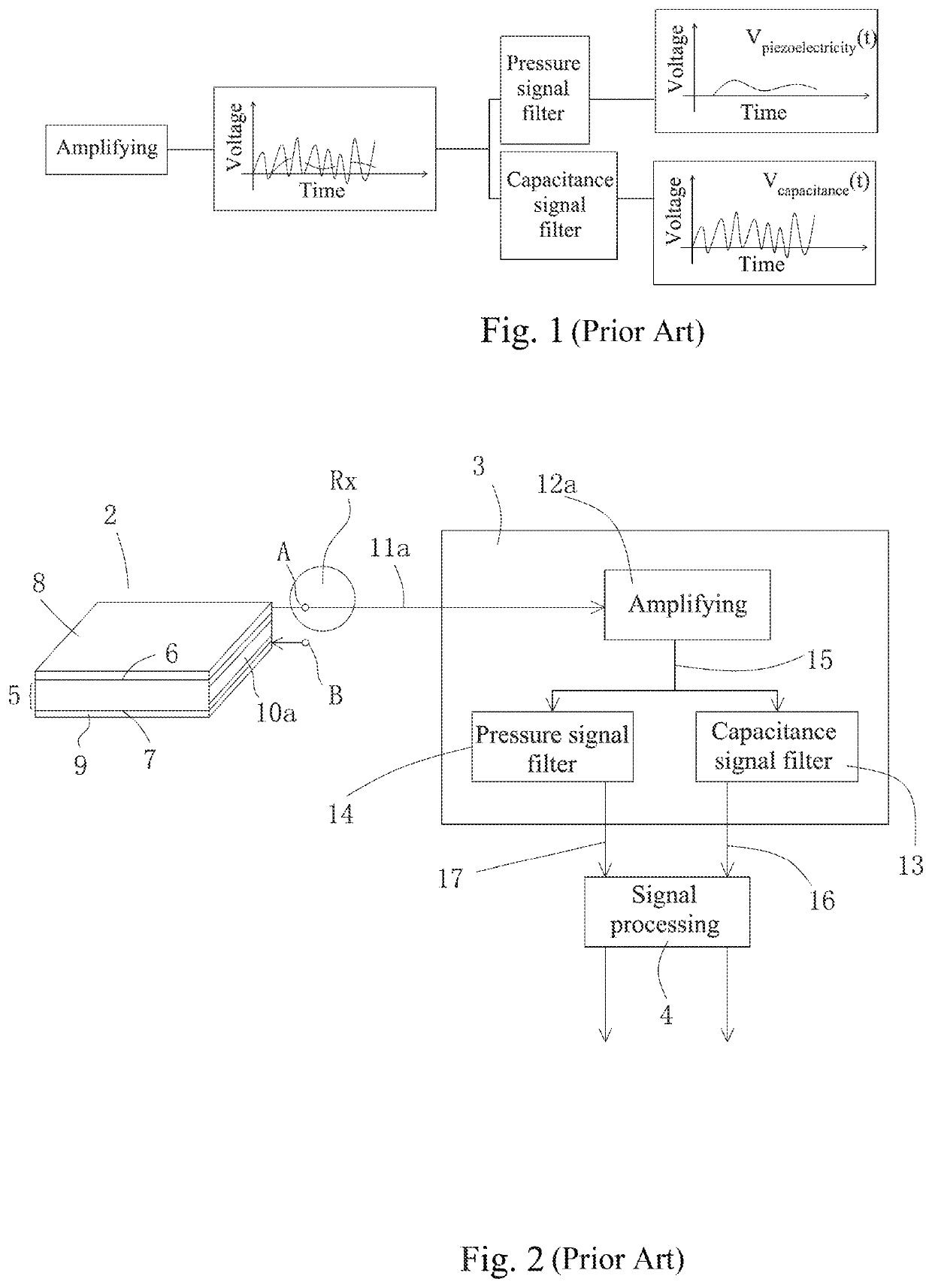
However, electrical signal interference in the three-dimensional touch module is very serious, which reduces the measurement accuracy of the touch position and pressure value.
Therefore, how to extract the touch signal and the pressure signal at the same time is a big challenge for the control module.
(1) The extracted touch signal and pressure signal are mixed, making it more difficult to extract the pressure signal.
(2) The signal processing technology is complex, the requirements for the control module are high, and the signal interference problem is serious.

Method used


Image

  • Three-dimensional touch module and detection method thereof
  • Three-dimensional touch module and detection method thereof
  • Three-dimensional touch module and detection method thereof

Examples


Embodiment Construction

[0046]Reference will now be made in detail to the present embodiments of the disclosure, examples of which are illustrated in the accompanying drawings. Wherever possible, the same reference numbers are used in the drawings and the description to refer to the same or like parts. However, specific structural and functional details disclosed herein are merely representative for purposes of describing example embodiments, and thus may be embodied in many alternate forms and should not be construed as limited to only example embodiments set forth herein. Therefore, it should be understood that there is no intent to limit example embodiments to the particular forms disclosed, but on the contrary, example embodiments are to cover all modifications, equivalents, and alternatives falling within the scope of the disclosure.

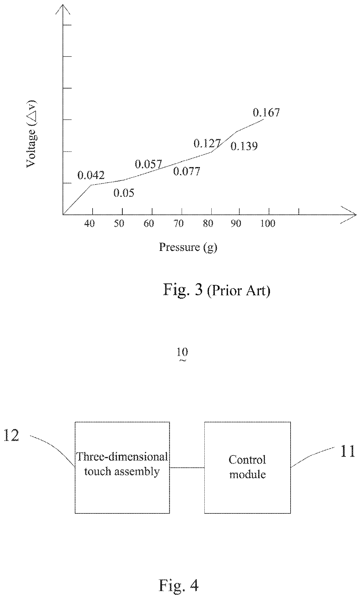
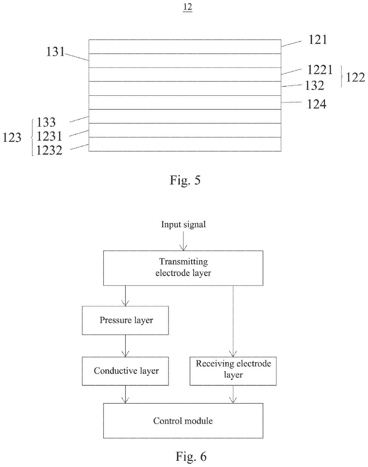
[0047]Reference is made to FIG. 4 with reference to FIG. 5. A first embodiment of the present embodiment provides a three-dimensional touch module 10, which includes a con...


PUM


Abstract

A detection method of a three-dimensional touch module includes: step S1, providing an input signal to a transmitting electrode layer; step S2, outputting a first output signal and transmitting the first output signal to a control module by a two-dimensional inputting assembly, and outputting a second output signal and transmitting the second output signal to the control module by a pressure sensing assembly; and step S3, determining, by the control module, a touch position according to the first output signal and a pressure value according to the second output signal. A three-dimensional touch module includes: a cover plate; a two-dimensional inputting assembly disposed under the cover plate and configured to output a first output signal; a pressure sensing assembly disposed under the cover plate and configured to output a second output signal; and a transmitting electrode layer disposed between the two-dimensional inputting assembly and the pressure sensing assembly.

Description

CROSS-REFERENCE TO RELATED APPLICATION[0001]This application claims priority to China Application Serial Number 202010229000.4, filed Mar. 27, 2020, which is herein incorporated by reference.BACKGROUNDTechnical Field[0002]The present disclosure relates to touch input technology, and more particularly, to a three-dimensional touch module and a detection method thereof.Description of Related Art[0003]With the development of touch technology, display devices equipped with touch functions have been maturely applied to industrial electronics and consumer electronics products. For the detection of a touch point, whether on a capacitive screen or a resistive screen, different principles are used to determine the two-dimensional coordinates of the touch point on the display device and establish a two-dimensional coordinate system (X, Y). The detection of the touch point is equivalent to determining the position of the touch point in the X-axis direction and the position in the Y-axis direct...

Claims


Application Information

Patent Timeline
IPC IPC(8): G06F3/041G06F3/044
CPCG06F3/0416G06F3/045G06F3/0445G06F3/0414G06F3/044G06F2203/04105G06F3/043G06F2203/04101
Inventor YE, CAI JINCHUANG, CHIH-CHENGLEE, LIEN-HSINWEI, TSAI-KUEILIN, SUN POWANG, REN-HUNGCHAN, YU-TINGCHENG, TAI-SHIHZHAO, YAN
Owner TPK TOUCH SOLUTIONS (XIAMEN) INC
Learn More