Animal keeping installation

a technology for installing and keeping animals, applied in the field of animal keeping installation, can solve the problems of difficult to realize in a simple, functionally reliable and cost-effective manner, mat torn to pieces, operating disturbances and breakdowns, etc., and achieve the effect of simple, functionally reliable and cost-effectiv

Active Publication Date: 2014-08-21
LINDVALL TOMMY
View PDF5 Cites 0 Cited by
  • Summary
  • Abstract
  • Description
  • Claims
  • Application Information

AI Technical Summary

Benefits of technology

[0009]The object of the present invention is to provide a new type of drive device which, in a simple, functionally reliable and cost-effective manner, solves the propulsion problems for a matted floor of an animal keeping installation.

Problems solved by technology

The construction can be realized in many different ways, but has proved difficult to realize in a simple, functionally reliable and cost-effective manner.
One problem is that the driving of the endless mat of the floor tends to skew the mat in relation to the drive roll, which means that the mat slides against mountings and bearings, which causes the mat to be torn to pieces and results in operating disturbances and breakdowns.

Method used


Image

  • Animal keeping installation
  • Animal keeping installation
  • Animal keeping installation

Examples


second embodiment

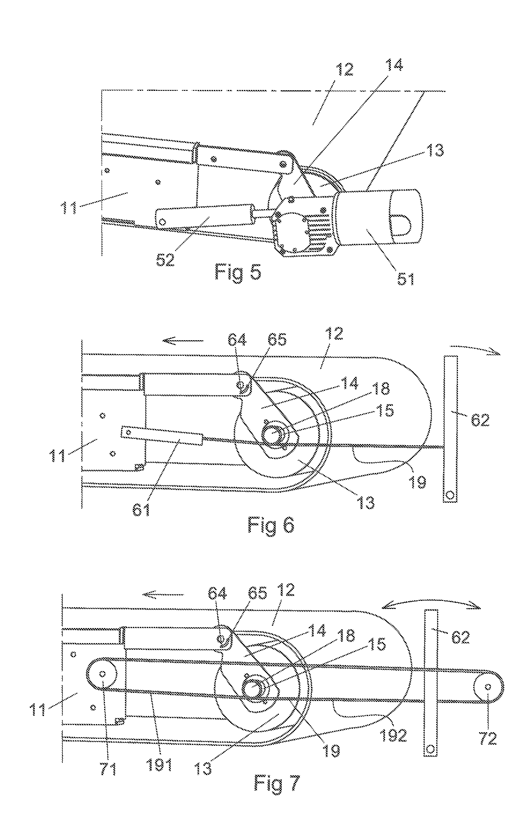
[0038]FIG. 5 shows the invention. In this embodiment, the floor 11 of the animal keeping installation is constantly horizontally orientated. The floor 11 according to this embodiment is provided with an endless mat 12, which at one end of the floor runs around a drive roll 13. The drive roll is rotatably mounted and suspended in a pendulum 14, so that the drive roll can assume an active driving position when it engages against the inner side of the mat and an inactive operating position when the pendulum swings the roll away from the engagement. For driving the drive roll 13, a drive motor 51 is mounted at the pendulum 14, which drive motor can be driven continuously or controlled intermittently for driving of the drive roll in those positions where the drive roll bears against the mat 12. In addition, a hydraulic cylinder, such as a pendulum drive member 52, is controlled to actuate the movement of the pendulum 14 between a drive position and a rest position. The controlling of the...

first embodiment

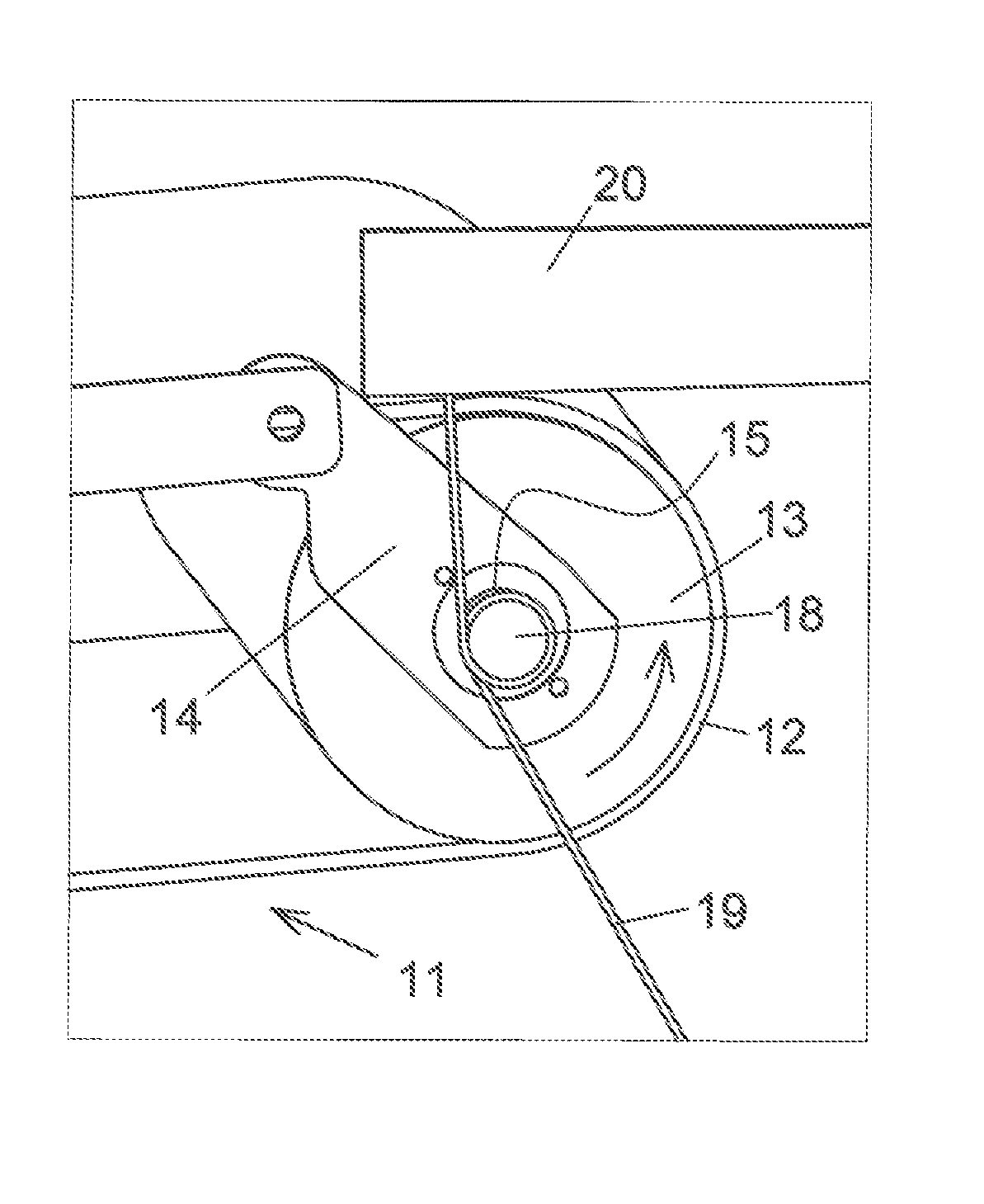
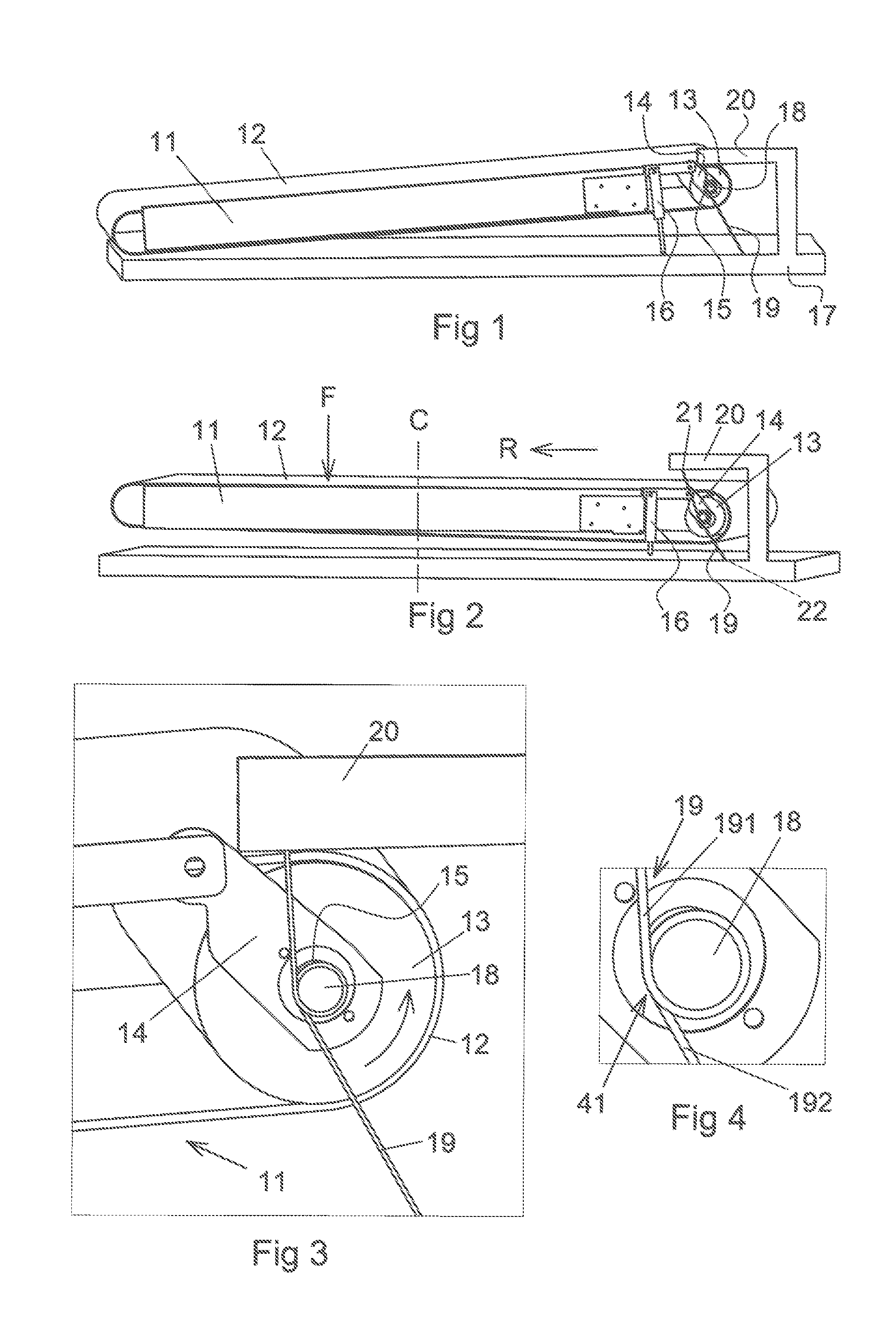
[0039]FIG. 6 shows a further embodiment of the invention, in which the floor 11 with its endless mat 12 is held horizontally in the same way as the floor in the embodiment shown in FIG. 5. The drive roll 13 is suspended by means of bearings in a pendulum 14 rotatably fixed in the floor 11, in a corresponding manner to that shown in FIGS. 1-5. Between a drive cable 19, which is reeled around a drive journal 18, and the floor 11 is connected a spring member 61, which exerts a force upon the cable and thus the pendulum, which force is intended to displace the pendulum and thus the drive roll 13 away from bearing contact against the inner side of the mat 12. The spring member 61 thus causes a gap to be formed between the drive roll and the mat when the spring member is in its rest position. In a similar manner to that shown in the first embodiment, the drive journal 18 is fixedly connected to the bearing journal 15 of the drive roll 13 for rotation about the centre axis of the drive rol...


PUM


Abstract

Animal keeping installation comprising a floor (11) provided with a mat (12) on which the animal treads when setting foot on the floor(11) and which mat (12) is arranged to be intermittently propelled by a drive roll (13) placed internally in relation to the mat (12), wherein the drive roll (13) is connected to and mounted in bearing journals (15) for rotation about its centre axis in a pendulum(14) which allows the drive roll (13), on the one hand, to bear against the inner side of the mat (12) and, on the other hand, to be released from the said bearing contact in dependence on the position of the pendulum (14), and wherein the drive roll (13) is connected to a drive member (18, 19, 15, 62) for driving the roll (13) at least into a position where the drive roll (13) bears against the mat (12).

Description

TECHNICAL FIELD[0001]The present invention relates to an animal keeping installation comprising a floor which comprises a preferably endless mat, which mat is intermittently driven in one direction in order, for example, to remove droppings from the floor and apply bedding and / or fodder to the same.BACKGROUND TO THE INVENTION[0002]The background to the invention can be seen from Swedish patent application SE 0100830-9 with publication number SE 520871, with equivalence in U.S. Pat. No. 7,051,680. This publication shows an animal keeping installation having a floor, a tending device and a drive device for the tending device. The drive device acts upon the floor, which is driven by an animal, through movement, subjecting the floor to a dynamic load which causes an energy-absorbing device to absorb energy, which is later released and produces driving of the floor.[0003]The said publication shows in one embodiment an energy storage through tensioning of a helical spring, which stored en...

Claims


Application Information

Patent Timeline
Patent Type & Authority Applications(United States)
IPC IPC(8): A01K1/01
CPCA01K1/0135A01K1/0117A01K15/027
Inventor LINDVALL, TOMMY
Owner LINDVALL TOMMY
Why Eureka
Try Eureka