Millimeter-wave sensor system for parking assistance

a sensor system and millimeter wave technology, applied in the field of parking support apparatus, can solve the problems of inability to get information if the obstacle is visible, and high cost of such system with antenna and assembly

Active Publication Date: 2019-12-10
NOVELIC D O O
View PDF15 Cites 7 Cited by
  • Summary
  • Abstract
  • Description
  • Claims
  • Application Information

AI Technical Summary

Benefits of technology

[0022]This invention proposes an Apparatus 100 and Method of Operation for inherently low-complexity and low-cost topology mm-wave radar sensor, targeting as a major application field vehicle parking support.
[0067]The proposed apparatus and method of operation allows the production of the complete sensor system in the cost range significantly lower than 2€, per piece, for higher quantities, which is presented as one or more orders of magnitude cost difference compared to current state of the art solutions. This is only possible by using the proposed special integrated circuitry and antenna systems and specific semiconductor technology.
[0069]If the parking support sensor is realized in a way that more than one Apparatus 100 is used on one side of the vehicle, in that case the complexity of Apparatus 100 may be dramatically reduced, by completely omitting the FMCW type of operation for distance detection and concentrating only on angular calculations. This means that if we have the angular information of the object obtained from more than one Apparatus 101, we may calculate its position and distance to the vehicle by simple calculation means. This means that no fractional N PLL is required, which requires a lot of space and complexity and also that there is no need for FMCW signals processing in signal processing units.
[0070]Proposed Apparatus 101 has a subset of the hardware complexity of Apparatus 100 and may be realized with significantly lower costs compared to Apparatus 100. However, it requires an additional vehicle calculation entity, which may be realized as an extra software application component of the vehicle's main computation unit. The system approach with Apparatus 101 does not offer optional features of living being detection by Doppler CW mode of operation.
[0089]Proposed Apparatus 101 may be realized in a way that the transmitting and receiving functionalities are separated, like in FIG. 8. In this case we are recognizing two Apparatuses: Apparatus 102a for the transmitting functionality and Apparatuses 102b for the receiving functionality. This approach allows for even lower system cost, meaning that for one side of the vehicle we may use one transmitter and several receiver options, meaning also that the silicon and complexity cost for each specific item is also reduced. So we would theoretically need one Apparatus 102a and two Apparatuses 102b for one side of the vehicle. By this approach each of the Apparatuses 102 have a reduced requirements for antennae, so the antenna structures may be advantageously released on the mm-wave chip, which may positively influence the sensor module cost by the reduction of the assembly cost.

Problems solved by technology

This approach has an inherent drawback, in that sensors integrated in the vehicle are visible.
This is due to the nature of ultrasound propagation properties, where the bumper material does not allow for propagation of the ultrasound in an easy and usable manner.
The driver is provided with the information about the existence of the obstacle, but is unable to get information if the obstacle could potentially be a living being, like a cat or a dog.
The cost of such system with antenna and the assembly is high, with mm-wave IC typically realized in SiGe BiCMOS technology.
Millimeter-wave radar systems could be integrated in the vehicle bumper, but having communication losses and system topologies of mm-wave sensors and methods of operation, do not allow for low system cost.
The number of transmit and receive channels is too high, power levels are too high, the dynamic range is not adjusted for special applications and a complicated signal processing is required.

Method used


Image

  • Millimeter-wave sensor system for parking assistance
  • Millimeter-wave sensor system for parking assistance
  • Millimeter-wave sensor system for parking assistance

Examples


Embodiment Construction

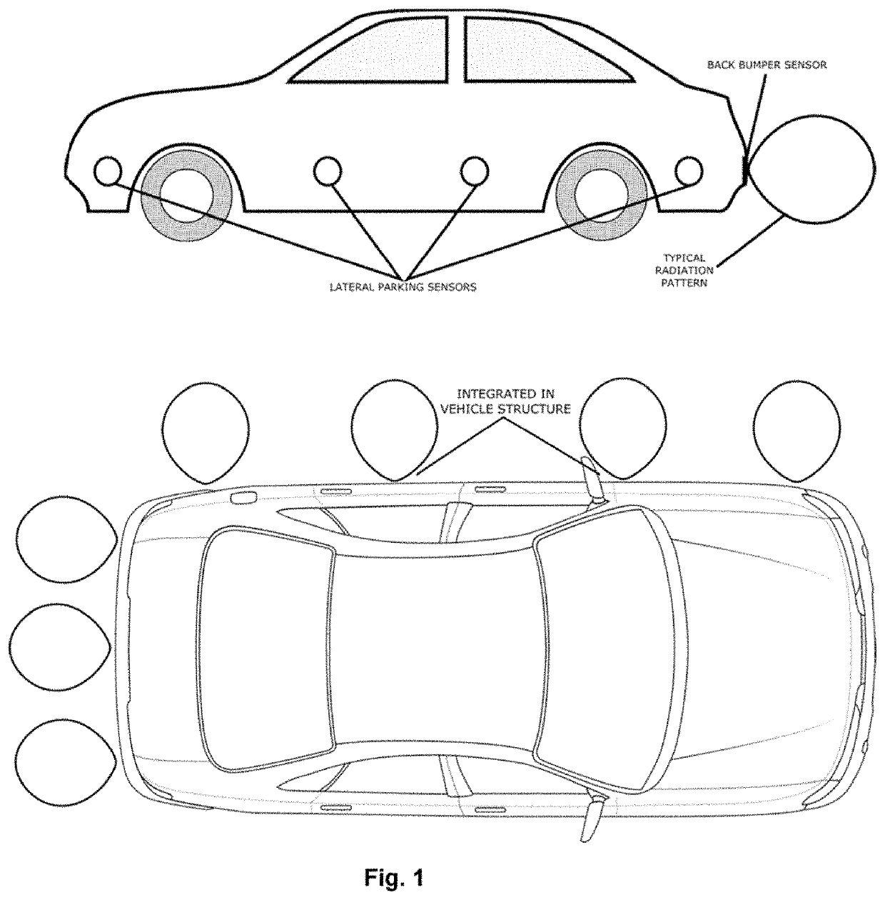
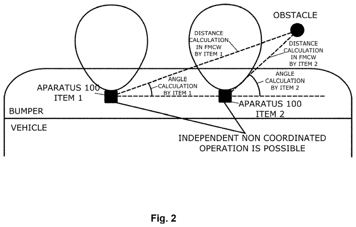
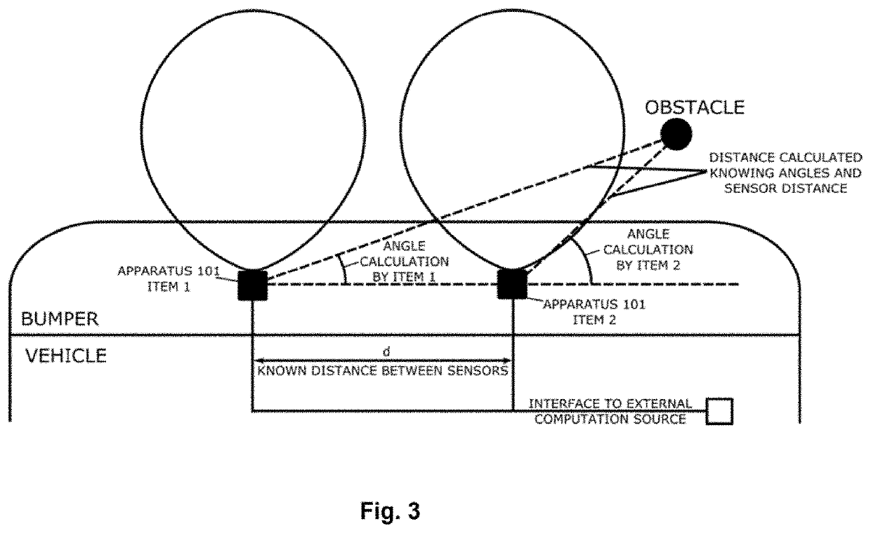
[0105]The proposed apparatuses 100, 101, 102a and 102b perform calculation of the distance and angle of the obstacle. The Apparatus 100 allows additionally and optionally to explore the parking obstacles vibrations, being able to detect a living being, in case of vital signs detection.

[0106]Entity 100 enables three different modes of radar operation:[0107]FMCW operation for distance calculation[0108]CW mode for parking obstacle angle calculation, with sets of power detectors and optional[0109]Doppler type of operation in CW mode, for vibration detection.

[0110]The proposed invention has in entity 10 fractional N PLL being able to address the complete frequency band of operation, being regulatory allocated for the operation of the devices. In case of automotive frequency band 77-81 GHz, the PLL is addressing the full 4 GHz bandwidth, which allows high resolution bandwidth, also without special digital processing techniques. Through frequency ramp bandwidths of up to 10 GHz, in mm-wave...


PUM


Abstract

The present invention relates to a parking support Apparatus and Method of operation comprising of an mm-wave radar sensor, having an integrated mm-wave IC front end. The proposed Apparatus is capable of detecting the parking obstacle object distance and angle, having inherently low cost system topology, suitable as a replacement in functionality for the commonly used ultrasound sensors. The proposed apparatus topology consist of one transmitting and two planar antennae, mm-wave radar topology with one down conversion chain and one transmitter chain based on FMCW radar, CW radar and Doppler radar, analog combining circuitry and N mm-wave power detectors, where N takes integer values from 1 and larger. The specific proposed method of operation is adjusted to a dedicated application. A combination of more than one proposed apparatus enables smart observation of the parking area in front of the moving platform with wired or wireless connection to the information evaluation and control entity. The proposed apparatus topology with lower complexity consist of one transmit and two planar antennae, mm-wave radar topology without any down conversion chain and one transmitter chain based on CW radar operation, analog combining circuitry and N mm-wave power detectors, where N takes values from 1 to 3. The system operation topology allows full distance and obstacle angle calculation by the apparatus itself in one topology solution or to have the information being calculated, combining more sensors, using low complexity apparatus topologies, also proposed in this innovation. The integration of the proposed apparatus in the vehicle bumper is inherently possible and may be optically and functionally provided as an efficient replacement for ultrasound parking assist systems. The complete proposed sensor apparatus topologies with integrated antennae, mm-wave IC and digital processing parts may be realized in a module smaller than 1×1×0.5 cm and operating in the 77-81 GHz band.

Description

TECHNICAL FIELD[0001]The present invention relates to a parking support Apparatus and Method of Operation comprising of mm-wave radar sensor with integrated mm-wave IC Front and having innovative topology. The proposed Apparatus is capable of detecting the object distance and parking obstacle angle, having inherently low cost system topology and is suitable as a functional replacement for the commonly used ultrasound sensors. The proposed Apparatus topology consists of one transmitting and two receiving planar antennae, mm-wave radar topology, analog combining circuitry and N mm-wave power detectors, where N takes integer values from 1 and higher. The mm-wave radar topology consists of one down conversion chain and one transmitter chain based on FMCW radar, CW radar and Doppler radar operation principles. Specific proposed method of operation is proposed to provide the specific proposed Apparatus operation.BACKGROUND ART[0002]There is a strong motivation to deploy smart, small in si...

Claims


Application Information

Patent Timeline
Patent Type & Authority Patents(United States)
IPC IPC(8): G01S13/93G01S13/44G01S13/87G01S13/58G01S13/931
CPCG01S13/878G01S13/584G01S13/931G01S13/4445G01S2013/9385G01S2013/9389G01S2013/9314G01S7/282G01S7/285G01S13/08G01S2013/93274G01S2013/93272G01S2013/93275
Inventor TASOVAC, DARKOMIHAJLOVIĆ, VELJKOBRANKOVIĆ, VESELINKR{HACEK OVER (C)}UM, DU{HACEK OVER (S)}ANMILOSAVLJEVIĆ, IVAN
Owner NOVELIC D O O
Why Eureka
Try Eureka