
Numerical controller

a controller and number technology, applied in the field of numerical controllers, can solve the problems of time until the punch tool attached to and the time until the punch head touches the workpiece becomes a dead time, and achieve the effect of shortening the cycle time and avoiding the dead tim

Active Publication Date: 2019-12-24
FANUC LTD
View PDF8 Cites 0 Cited by
  • Summary
  • Abstract
  • Description
  • Claims
  • Application Information

AI Technical Summary

Benefits of technology

This solution prevents dead time generation, allowing for shorter cycle times during tool exchange or obstacle avoidance, thereby improving the efficiency of punch press machining.

Problems solved by technology

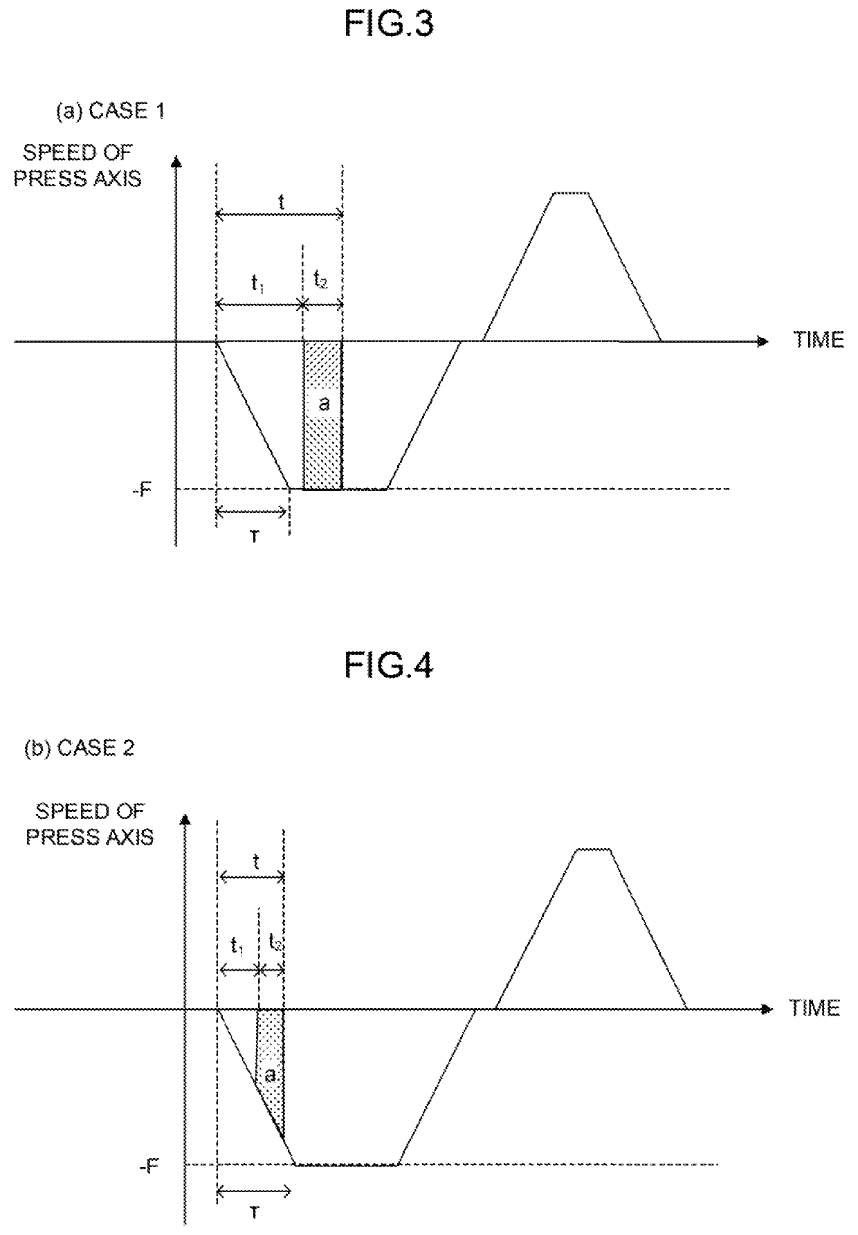
Thus, if press starts at the same timing in a case in which the punch head rises to a higher position than the rising edge immediately after tool exchange or after avoidance of an obstacle, for example, so that the stroke increases, then movement of the punch point to a position of the punch tool on the X / Y axis is completed at a point in time at which the overlap time elapses as illustrated in FIG. 9, and then a problem that the time until the punch tool attached to the punch head touches the workpiece becomes a dead time arises.

Method used


Image

  • Numerical controller
  • Numerical controller
  • Numerical controller

Examples


Embodiment Construction

[0022]A configuration example of a numerical controller for implementing the invention will be described below. However, a configuration of the numerical controller of the invention is not limited to the examples below, and any configuration may be adopted as long as an object of the invention can be achieved.

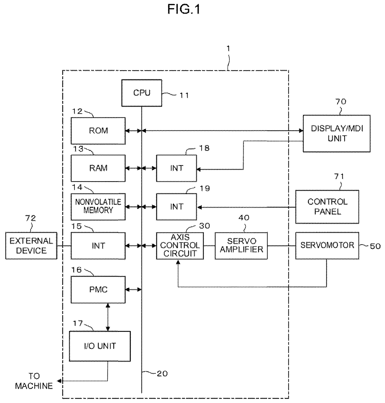
[0023]FIG. 1 is a schematic hardware configuration diagram illustrating a main part of a numerical controller according to an embodiment and a machine tool driven and controlled by the numerical controller.

[0024]A numerical controller 1 according to the present embodiment includes a central processing unit (CPU) 11. The CPU 11 reads a system program stored in a read only memory (ROM) 12 via a bus 20, and controls the entire numerical controller 1 according to the system program. A random access memory (RAM) 13 stores temporary calculation data, display data, various data input by an operator via a display / manual data input (MDI) unit 70 to be described below, etc.

[0025]A nonvol...


PUM

PropertyMeasurementUnit
overlap timeaaaaaaaaaa
overlap time calculationaaaaaaaaaa

Abstract

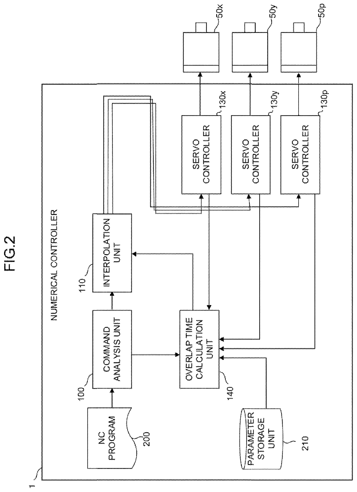
A numerical controller generates movement command data, and performs an interpolation process based on the generated movement command data to generate and output interpolation data. Further, in the case of a state in which a press operation in punch press machining is started from a different position from a position of a preset rising edge, an overlap time is calculated based on a position of a punch head when the press operation is started, and an output timing of interpolation data related to an axis controlling the press operation is controlled based on the calculated overlap time. In this way, even when there is a change in press stroke, a dead time may be prevented from being generated.

Description

CROSS-REFERENCE TO RELATED APPLICATION[0001]This application is a new U.S. Patent Application that claims benefit of Japanese Patent Application No. 2017-144071, filed Jul. 26, 2017, the disclosure of this application is being incorporated herein by reference in its entirety for all purposes.BACKGROUND OF THE INVENTION1. Field of the Invention[0002]The invention relates to a numerical controller, and particularly relates to a numerical controller that automatically adjusts press timing according to a press stroke.2. Description of the Related Art[0003]In punch press machine tools, a punch point on a workpiece is relatively moved to a position of a punch tool selected by a turret mechanism, etc. in a punch head based on a movement command for an X / Y axis commanded by a program, and then punch press machining is performed by a press operation (punch operation).[0004]As a conventional technology for increasing a speed of punch press machining by a punch press machine tool, there is a t...

Claims


Application Information

Patent Timeline
Patent Type & Authority Patents(United States)
IPC IPC(8): B21D28/26G05B19/19
CPCG05B19/19B21D28/26B21D28/265G05B2219/34083G05B2219/45137G05B19/41G05B19/4103G05B19/188G05B2219/43163
Inventor SATOU, TAKASHIMOCHIDA, TAKESHI
Owner FANUC LTD
Learn More