Steering system for vessel
a steering system and vessel technology, applied in the direction of steering initiation, vessel construction, marine propulsion, etc., can solve the problems of inability to dispose of automatic steering devices in some cases, and the on-board space available to the occupant of the vessel decreases, so as to achieve accurate grasping and simplify the base of the console
- Summary
- Abstract
- Description
- Claims
- Application Information
AI Technical Summary
Benefits of technology
Problems solved by technology
Method used
Image
Examples
second preferred embodiment
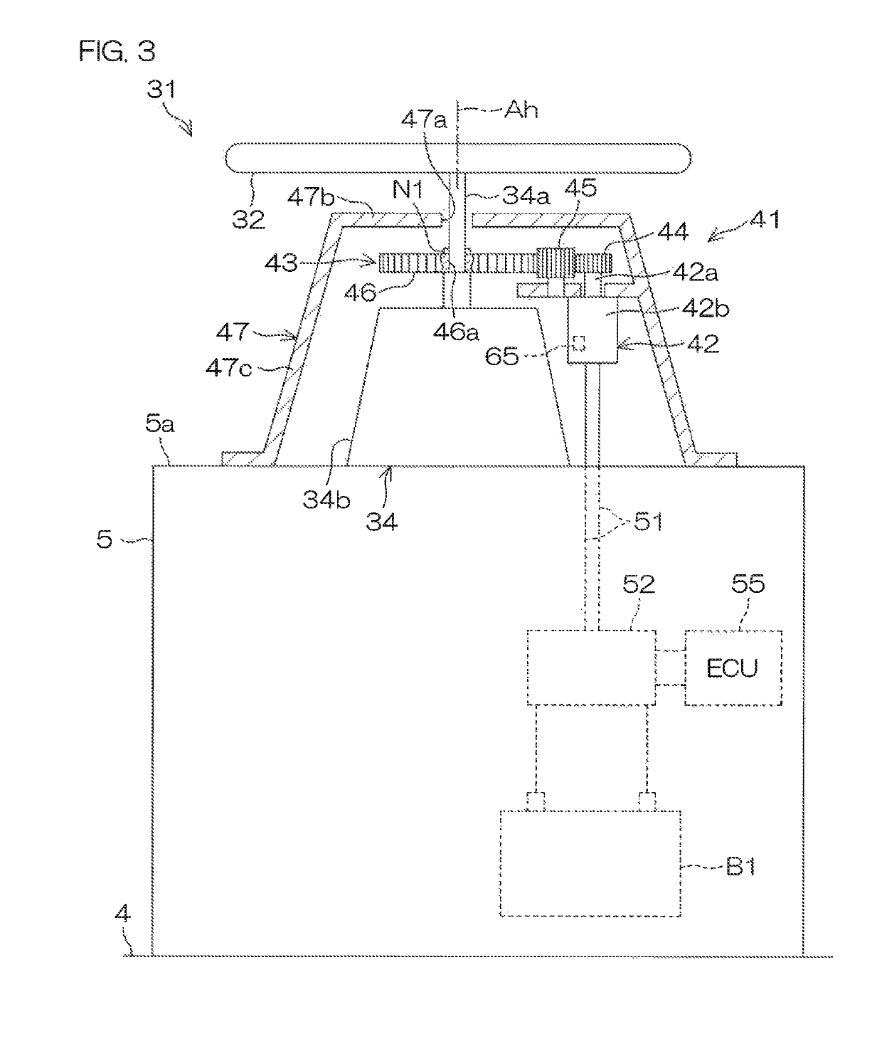
[0153]Next, a second preferred embodiment of the present invention will be described. In the following FIG. 10 to FIG. 13D, elements that are the same or substantially the same as the elements shown in FIG. 1 to FIG. 12 described above are denoted by the same reference symbols as those in FIG. 1 etc., to omit their description.
[0154]FIG. 10 is a schematic view showing an automatic steering device 41 according to the second preferred embodiment of the present invention. FIG. 11 is a block diagram for describing an electrical configuration of the automatic steering device 41. FIG. 12 is a schematic view for describing an angle range in which automatic steering is carried out.
[0155]A major difference between the second preferred embodiment and the first preferred embodiment is that, in place of the mobile terminal 59, a wind direction detector 71 that detects an inclination angle of a bow direction Db (direction from a stern center to a bow) with respect to a wind direction is provided...
third preferred embodiment
[0174]Next, a third preferred embodiment of the present invention will be described. In the following FIG. 14, elements that are the same or substantially the same as the elements shown in FIG. 1 to FIG. 13D described above are denoted by the same reference symbols as those in FIG. 1 etc., to omit their description.
[0175]FIG. 14 is a schematic view showing an automatic steering device 41 according to a third preferred embodiment of the present invention.
[0176]A major difference between the third preferred embodiment and the second preferred embodiment is that, in place of the drive circuit 78 and the drive switch 81, a wind direction rotation angle detector 90 that detects a rotation angle of the wind direction detector 71 (rotation angle of the indication direction Di) and a controller 55 that determines an inclination angle of the bow direction Db with respect to the wind direction based on the detection value of the wind direction rotation angle detector 90 are provided in the au...
fourth preferred embodiment
[0184]Next, a fourth preferred embodiment of the present invention will be described. In the following FIG. 15, elements that are the same or substantially the same as the elements shown in FIG. 1 to FIG. 14 described above are denoted by the same reference symbols as those in FIG. 1 etc., to omit their description.
[0185]FIG. 15 is a schematic view showing an automatic steering device 41 according to a fourth preferred embodiment of the present invention.
[0186]A major difference between the fourth preferred embodiment and the third preferred embodiment is that, in place of the wind direction detector 71 and the wind direction rotation angle detector 90, a direction detector 91 that detects an inclination angle of the bow direction Db with respect to a horizontal setting direction Ds that is set by the vessel operator is provided in the automatic steering device 41. An angle signal that is transmitted from the direction detector 91 to the controller 55 is an example of an input signa...
PUM
 Abstract
Description
Claims
Application Information
 - R&D
- Intellectual Property
- Life Sciences
- Materials
- Tech Scout
- Unparalleled Data Quality
- Higher Quality Content
- 60% Fewer Hallucinations
Browse by: Latest US Patents, China's latest patents, Technical Efficacy Thesaurus, Application Domain, Technology Topic, Popular Technical Reports.
© 2025 PatSnap. All rights reserved.Legal|Privacy policy|Modern Slavery Act Transparency Statement|Sitemap|About US| Contact US: help@patsnap.com


