
Planning and engineering method, software tool and simulation tool for an automation solution

a technology of automation and engineering methods, applied in the direction of program control, total factory control, instruments, etc., can solve the problems of increased susceptibility to cyber-attacks, high implementation costs, and difficult prediction of the behavior and effects of cyber-attacks on the overall behavior of the plant, so as to enhance the benefits of siem systems and reduce the risk of incorrect decisions

Active Publication Date: 2019-12-31
SIEMENS AG
View PDF15 Cites 0 Cited by
  • Summary
  • Abstract
  • Description
  • Claims
  • Application Information

AI Technical Summary

Benefits of technology

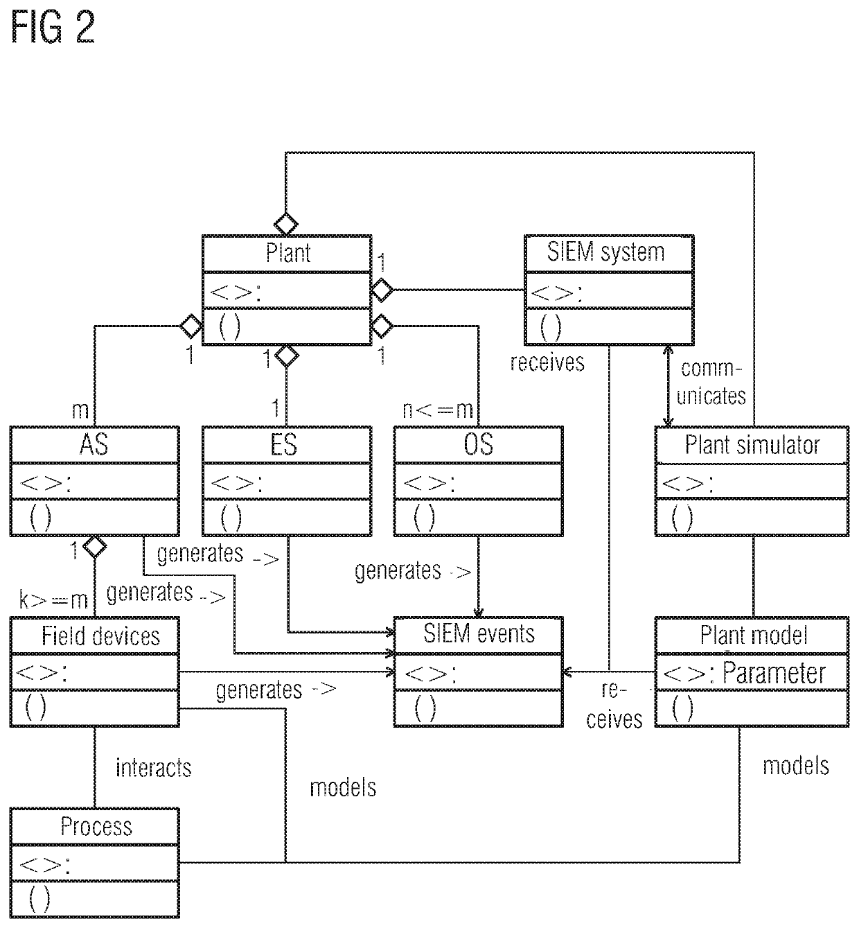
[0022]The SIEM correlation rules can be advantageously configured by means of an engineering tool and transferred into the SIEM system. Together with the objects that represent the operable and observable components of the plant and hardware components of the automation system, the properties and parameters of these components are stored in libraries of the engineering tool. Also belonging to the parameters are the security events that can be generated by the hardware components and which are described by attributes. When designing and configuring the automation solution, the library is accessed; the required components are selected and imported into the planning project, wherein the associated security events are also automatically created in the planning project. Plant-specific SIEM correlation rules can then be designed for the planning project, based on the security events that can be generated by the configured components. Graphical methods may be used to generate the SIEM correlation rules on the model of a flow diagram consisting of steps and transitions. If a security event occurs, a transition is executed and a new step is reached, in which by way of example a new security event can be generated, which in turn is used in the SIEM correlation rules. By modeling the correlation rules using a procedure description it is also possible to describe, for example, sequential events. In the event of changes in plant planning, such as the omission of a component, effects on the security events and on the SIEM correlation rules can be readily determined. The configuration of SIEM correlation rules is therefore integrated into the configuration of the automation solution and is thus more plant-specific and automation-specific and is more efficient than heretofore attainable.
[0030]The response of the SIEM system can actively influence the control system, which was not hitherto possible for security reasons. Thanks to the simulative verification of the SIEM system, the determinacy of the plant behavior can be guaranteed.

Problems solved by technology

As a consequence, the automation of processes in industrial plants also represents an IT (information technology) complex and infrastructure that is critical to security and is under increased susceptibility to cyber-attacks.
This relates to very complex systems of rules and events, the behavior and effects of which on the overall behavior of the plant are not easy to predict.
The cost of implementation is very high and testing for full functionality and coverage is not easy to achieve.
When deploying a SIEM system in an industrial plant, the active use of such extended functionality is however generally dispensed with, because the action triggered by the SIEM system can negatively impact the normal operation of the plant and could possibly result in endangering the process and / or human lives.
Yet because of the complexities involved, suitable actions of the plant operator and the resulting behavior of the plant cannot be determined and optimized until the plant is in operation.
The danger then is that errors in the planned code of practice for response to critical security incidents cannot be identified or inappropriate actions by operating personnel cannot be prevented.
There are quite simply insufficient opportunities for testing of the system in the context of the overall plant and plant management.

Method used


Image

  • Planning and engineering method, software tool and simulation tool for an automation solution
  • Planning and engineering method, software tool and simulation tool for an automation solution

Examples


Embodiment Construction

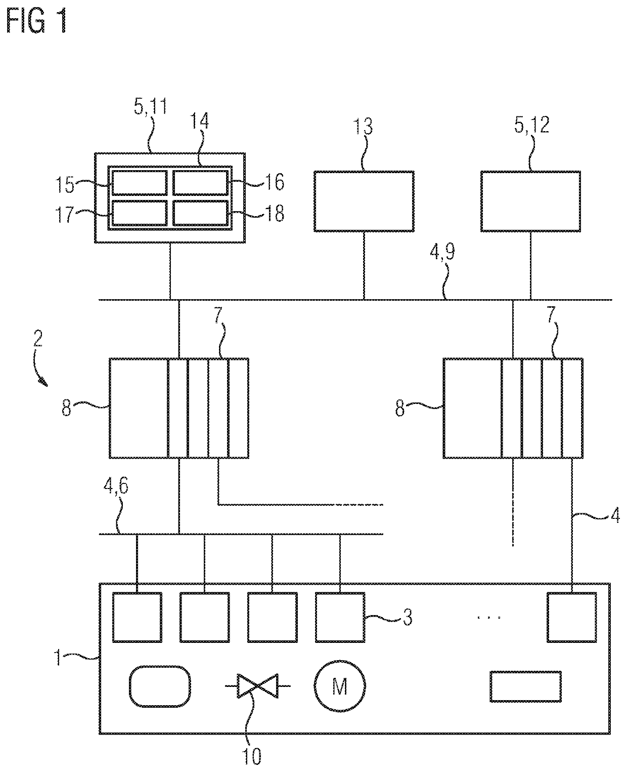
[0036]FIG. 1 depicts, in a simplified schematic representation and by way of illustrative example, a technical plant 1 in which a process is running under the control of an automation system 2. The automation system includes a plurality of process-oriented components (field devices) 3 which perform measurement, control and regulation functions predefined at field level, i.e. in the process, and in particular capture measured variables from the process and act on the process using control actions. The field devices 3 may by way of example be sensors, actuators, measuring transmitters, analysis devices, and drives, among others. The field devices 3 exchange process-related, function-related and / or device-related data with one another via a generally wired communication system 4 and with computer systems 5 at a control and planning level, to which end the field devices 3 are connected by (for example) a field bus 6 to input and output modules 7 of automation devices 8 (such as programm...


PUM


Abstract

In planning and engineering an automation solution which comprises an automation system and a process engineering plant, objects that represent the components of the configured automation solution are imported by means of a simulation tool to simulate the automation solution on the basis of simulation models associated with the imported objects. Attributes contained in objects which represent the hardware components of the automation system and which describe IT security events that may be generated by the components are entered into the associated simulation models for simulatively generating security events in a simulation of the automation solution, for transferring the simulatively generated security events to a Security Information Event Management (SIEM) system for evaluation, and for using the results of the evaluation generated by the SIEM system to simulate the automation solution.

Description

FIELD OF THE INVENTION[0001]The present invention relates to a planning and engineering method for an automation solution which comprises an automation system and a process engineering plant, wherein when designing and configuring the automation solution objects that are created and linked by means of an engineering tool and which represent operable and observable components of the plant and hardware components of the automation system are imported by a simulation tool and the automation solution is simulated using simulation models that are associated with the imported objects.BACKGROUND OF THE INVENTION[0002]The function of automation technology is to automate technical processes. Broadly, an automated system consists of a technical system (plant) in which the process runs, an automation process, and operating personnel. The automated process may, by way of illustrative example, be a processing or manufacturing technology process or a process for generating or distributing electri...

Claims


Application Information

Patent Timeline
Patent Type & Authority Patents(United States)
IPC IPC(8): G06F17/50G05B19/418G05B17/02H04L29/06G06F21/55
CPCH04L63/1433H04L63/20G06F21/552G06F17/509G05B19/41885G06F17/5009G05B17/02G05B2219/32339Y02P90/20Y02P90/26G05B19/4188G05B2219/32085Y02P90/02G06F30/18G06F30/20
Inventor DRUMM, OLIVERLUTZ, BENJAMINPALMIN, ANNAWOLF, GERRIT
Owner SIEMENS AG
Learn More