
Thermo-electrochemical converter

a technology of electrochemical cells and converters, applied in the direction of fuel cell combinations, regenerative fuel cells, fuel cells, etc., can solve the problems of high cost, low heat transfer efficiency, and inability to use cells, etc., to achieve high interface area and thermal conductivity, and facilitate effective heat transfer

Active Publication Date: 2019-12-31
JTEC ENERGY INC
View PDF23 Cites 0 Cited by
  • Summary
  • Abstract
  • Description
  • Claims
  • Application Information

AI Technical Summary

Benefits of technology

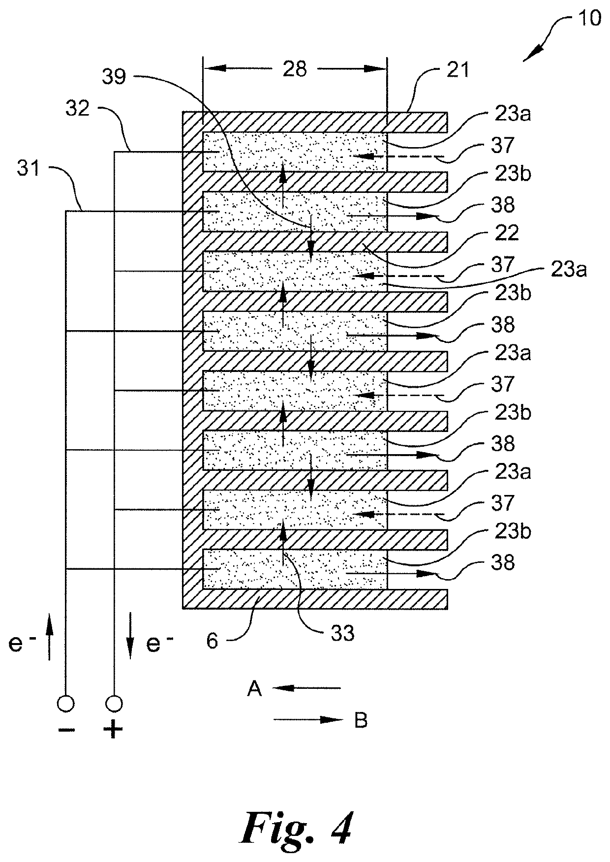
[0032]In one embodiment, the MEA stack is preferably made of ceramic materials and has a co-sintered structure. In another embodiment, the MEA stack is preferably made of polymeric materials and has a fused structure. Co-sintering or fusing of the components of the MEA stack allows for a practical construction of a large membrane area within a relatively small volume, while avoiding the complications and challenges associated with construction of individual cells and then making individual interconnects including flow manifolds, seals and electrical connections. The electrochemical cells or MEA stacks of the present invention also preferably operate on pressure differentials.
[0033]I have also surprisingly discovered that in-plane flow of the working fluid within thin electrodes enables construction of MEA stacks having high energy conversion density. This is unexpected, considering that existing fuel cell art teaches against in-plane flow of reaction fluids within thin electrodes. Specifically, existing fuel cell art teaches that electrodes should be thin, but that flow through the electrode should be perpendicular to the ion conductive membrane (i.e., not in-plane), in order to minimize concentration polarization effects.
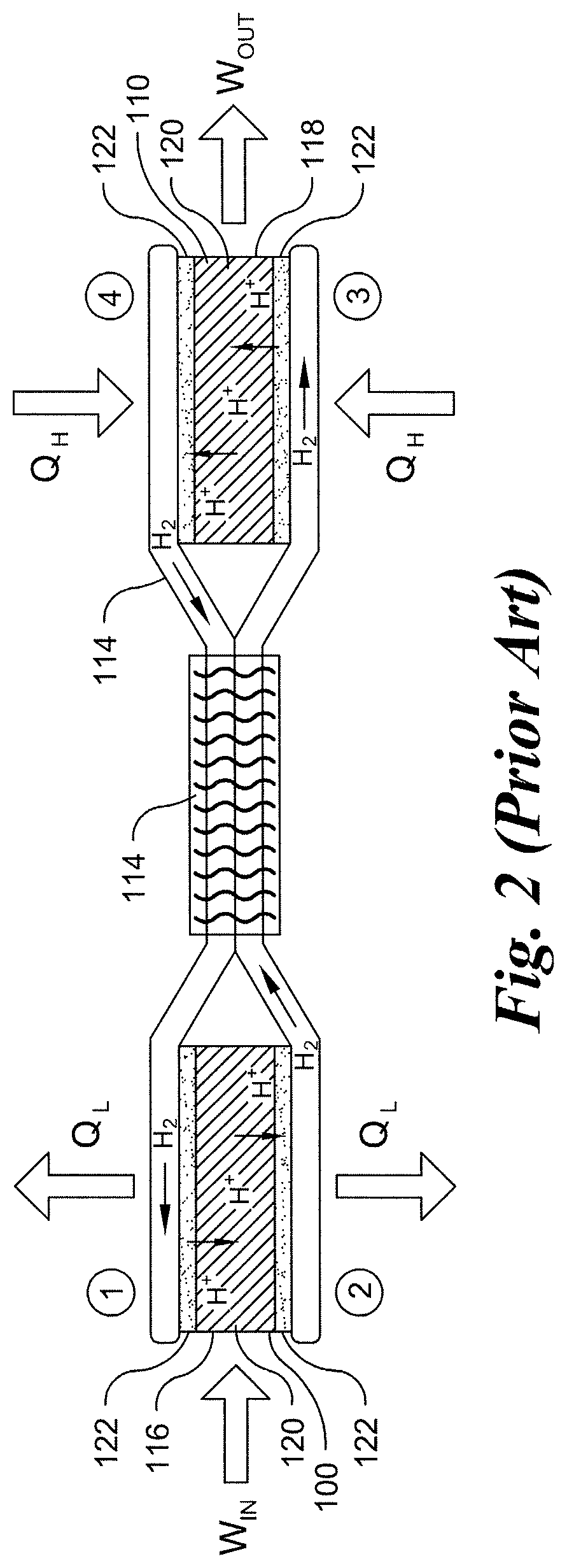
[0038]In one embodiment, sections of the high pressure channels and sections of the low pressure channels are preferably in physical contact with each other, and thus have a high interface area and thermal conductivity so as to facilitate effective heat transfer between working fluid in a high pressure channel and working fluid in a low pressure channel.
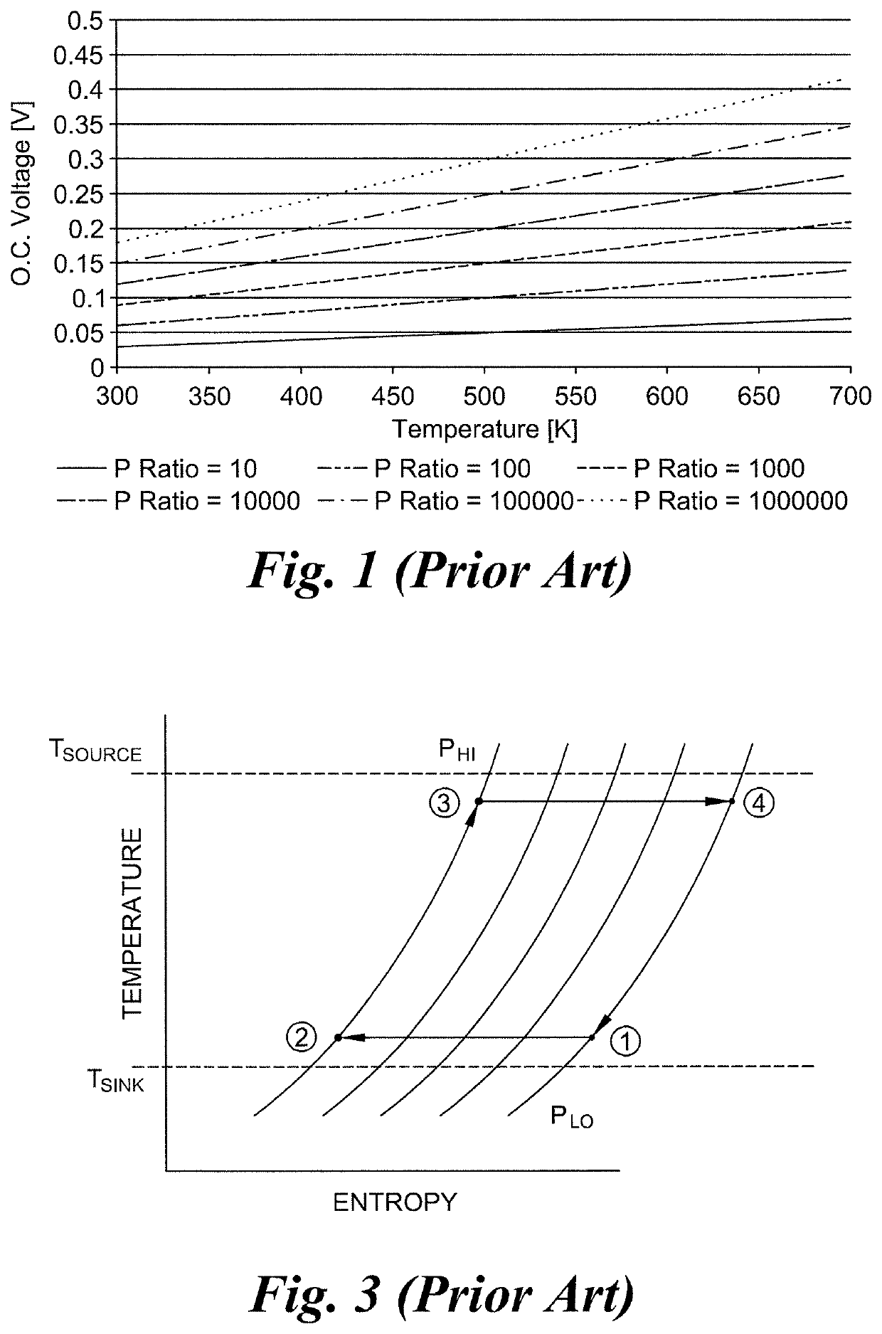
[0039]The heat exchanger of the co-sintered or fused heat engine preferably functions as a recuperative heat exchanger to recuperate heat from working fluid leaving the high temperature MEA stack by coupling it to working fluid flowing to the high temperature MEA stack. Providing such a recuperative heat exchanger in combination with a heat source and heat sink coupled to the high and low temperature electrochemical cells (i.e., MEA stacks) enables sufficient heat transfer for near constant temperature expansion and compression processes, thereby allowing the engine to approximate the thermodynamic Ericsson cycle.

Problems solved by technology

However, battery type electrochemical cells can produce only a limited amount of energy because the confines of the battery casing limit the amount of available reactants that may be contained therein.
Also, during the recharging process, the cell is typically not usable.
However, as with all mechanical engines, the Stirling engine suffers from reliability problems and efficiency losses associated with its mechanical moving parts.
AMTEC heat engines suffer from reliability issues due to the highly corrosive nature of the alkali metal working fluid.
AMTEC engines also have very limited utility.
Specifically, AMTEC engines can only be operated at very high temperatures because ionic conductive solid electrolytes achieve practical conductivity levels only at high temperatures.
However, some challenges have been encountered with developing a JTEC that is suitable for widespread use, particularly for systems that use hydrogen as the working fluid.
For example, hydrogen leakage through small defects in the conduit system may occur due to the small size of the hydrogen molecule.
In particular, hydrogen leakage can occur at the joints of the interconnects for the conduit couplings between the high-temperature cell and the low-temperature cell.
The engine design is also complicated by the need for a large membrane / electrode surface area and by the need for a significant number of cells to be electrically connected in series to achieve practical output voltage levels.
Further, in order to achieve efficient energy conversion, the membranes must have high diffusion barrier properties, because diffusion of working fluid (such as hydrogen gas) under the pressure differential across the membrane results in reduced electrical output and efficiency.
However, known and available membrane materials that have good ion conductivity, such as Nafion manufactured by the DuPont Corp., generally have very poor molecular diffusion barrier properties.
Conversely, known and available membrane materials that have high molecular diffusion barrier properties generally have relatively low ionic conductivity, and use of such materials would result is high system impedance and high polarization losses.
However, the cell will have low internal impedance if the ion conduction cross-sectional area of the membrane is too large.

Method used


Image

  • Thermo-electrochemical converter
  • Thermo-electrochemical converter
  • Thermo-electrochemical converter

Examples


Embodiment Construction

[0052]Certain terminology is used in the following description for convenience only and is not limiting. The words “proximal,”“distal,”“upward,”“downward,”“bottom” and “top” designate directions in the drawings to which reference is made. The words “inwardly” and “outwardly” refer to directions toward and away from, respectively, a geometric center of the device, and designated parts thereof, in accordance with the present invention. Unless specifically set forth herein, the terms “a,”“an” and “the” are not limited to one element, but instead should be read as meaning “at least one.” The terminology includes the words noted above, derivatives thereof and words of similar import.

[0053]It will also be understood that terms such as “first,”“second,” and the like are provided only for purposes of clarity. The elements or components identified by these terms, and the operations thereof, may easily be switched.

[0054]Referring to the drawings in detail, wherein like numerals indicate like ...


PUM

PropertyMeasurementUnit
thickaaaaaaaaaa
Nernst voltageaaaaaaaaaa

Abstract

A thermo-electro-chemical converter direct heat to electricity engine has a monolithic co-sintered ceramic structure or a monolithic fused polymer structure that contains a working fluid within a continuous closed flow loop. The co-sintered ceramic or fused polymer structure includes a conduit system containing a heat exchanger, a first high density electrochemical cell stack, and a second high density electrochemical cell stack.

Description

CROSS-REFERENCE TO RELATED APPLICATION[0001]This application is a Section 371 of International Application No. PCT / US2015 / 044435, filed Aug. 10, 2015, which was published in the English language on Feb. 18, 2016, under International Publication No. WO 2016 / 025372 A1, and which claims priority to U.S. Patent Application No. 62 / 035,560, filed Aug. 11, 2014, the disclosures of both of which are incorporated herein by reference in their entireties.BACKGROUND OF THE INVENTION[0002]The conversion of heat energy or chemical energy to electrical energy, or visa-versa, may be accomplished in a variety of ways. For example, known electrochemical cells or batteries rely on chemical reactions wherein ions and electrons of a reactant being oxidized are transferred to the reactant being reduced via separate paths. Specifically, the electrons are transferred electrically via wiring through an external load where they perform work and the ions are conducted through an electrolyte separator.[0003]Ho...

Claims


Application Information

Patent Timeline
Patent Type & Authority Patents(United States)
IPC IPC(8): H01M8/00H01M8/18H01M14/00
CPCH01M14/00H01M8/182H01M8/04029H01M8/04074Y02E60/50H01M2250/40
Inventor JOHNSON, LONNIE G.
Owner JTEC ENERGY INC
Learn More