Check patentability & draft patents in minutes with Patsnap Eureka AI!

System and methods for capture verification in implantable leadless pacemakers

a leadless pacemaker and capture verification technology, applied in the field of myocardial evoked response detection, can solve the problems of difficult to reliably measure an atrial er, battery size (and thus capacity) constraints, and severe engineering constraints regarding the size of their components, so as to reduce the burden on the processor

Active Publication Date: 2020-01-21
BIOTRONIK SE & CO KG
View PDF17 Cites 0 Cited by
  • Summary
  • Abstract
  • Description
  • Claims
  • Application Information

AI Technical Summary

Benefits of technology

[0012]Preferred versions of the invention involve methods and systems for detecting whether or not a pacing pulse results in myocardium capture, as evidenced by an evoked response (ER). These methods and systems seek to provide a voltage-based pacing scheme with a charge balancing phase that can be switched from passive balancing during normal pacing to an active current-based balancing technique during capture verification. The active charge balancing phase seeks to bring the post-pace open-circuit potential (OCP) difference between the pacing and return electrodes to its pre-pace value, thereby minimizing the polarization artifact caused by the biphasic pacing & balancing stimulus and allowing for robust ER sensing. The amplitude of the charge balancing pulse is such that it does not affect the threshold of the voltage pacing pulse compared to the threshold achieved with the normal passive balancing phase; the width of the charge balancing pulse is no longer than 5 ms or so (at most), so that early ER (e.g., atrial ER) might be more easily detected; and it utilizes pulses delivered during at least one, and preferably several, preceding cardiac refractory periods to determine a current pulse amplitude and pulse width to be used for charge balancing. These preceding pulses can be anodic and cathodic pulses delivered at the pacing electrode, with alternating passive and active charge balancing phases.
[0014]Preferred versions of the invention also seek to provide methods for ER signal processing and capture verification that do not require complicated mathematical operations or sophisticated computing power, thereby reducing processor burdens.

Problems solved by technology

Because leadless pacemakers must be made very small for optimal operation—typically smaller than a AAA battery—they are subject to severe engineering constraints regarding the size (and thus capacity) of their components.
Because their batteries must be small, the batteries typically have more limited energy storage capacity.
This is difficult owing to constraints regarding the size and computing ability of its electronics module.
It is known to be challenging to reliably measure an atrial ER in response to an atrial pacing pulse, as an atrial ER starts approximately 10 ms after pulse delivery, and it has much smaller amplitude than a ventricular ER (which starts around 60 ms following a ventricular pacing pulse).
However, the use of these coatings alone may not be sufficient to reduce artifacts to such an extent that the ER is easily discernable.
This approach can be difficult to practically implement in a leadless pacemaker, where size / space is critical, thereby making it highly desirable to use the same electrodes for pacing and sensing.
This approach also has drawbacks, as the capacitors needed to discharge the residual charge occupy additional space, posing challenges for minimizing the size of the pacemaker.
A disadvantage of these approaches is that they use current-based methods for stimulation pulses and for subsequent balancing (i.e., negation of polarization), and for better power efficiency and battery life, leadless pacemakers are preferably voltage-based stimulation devices, like traditional pacemakers.
These approaches also have drawbacks, as second order band-pass filters in the input circuit of a pacemaker may distort a polarization artifact to such an extent that it is falsely interpreted as an evoked response (ER).

Method used


Image

  • System and methods for capture verification in implantable leadless pacemakers
  • System and methods for capture verification in implantable leadless pacemakers
  • System and methods for capture verification in implantable leadless pacemakers

Examples


Embodiment Construction

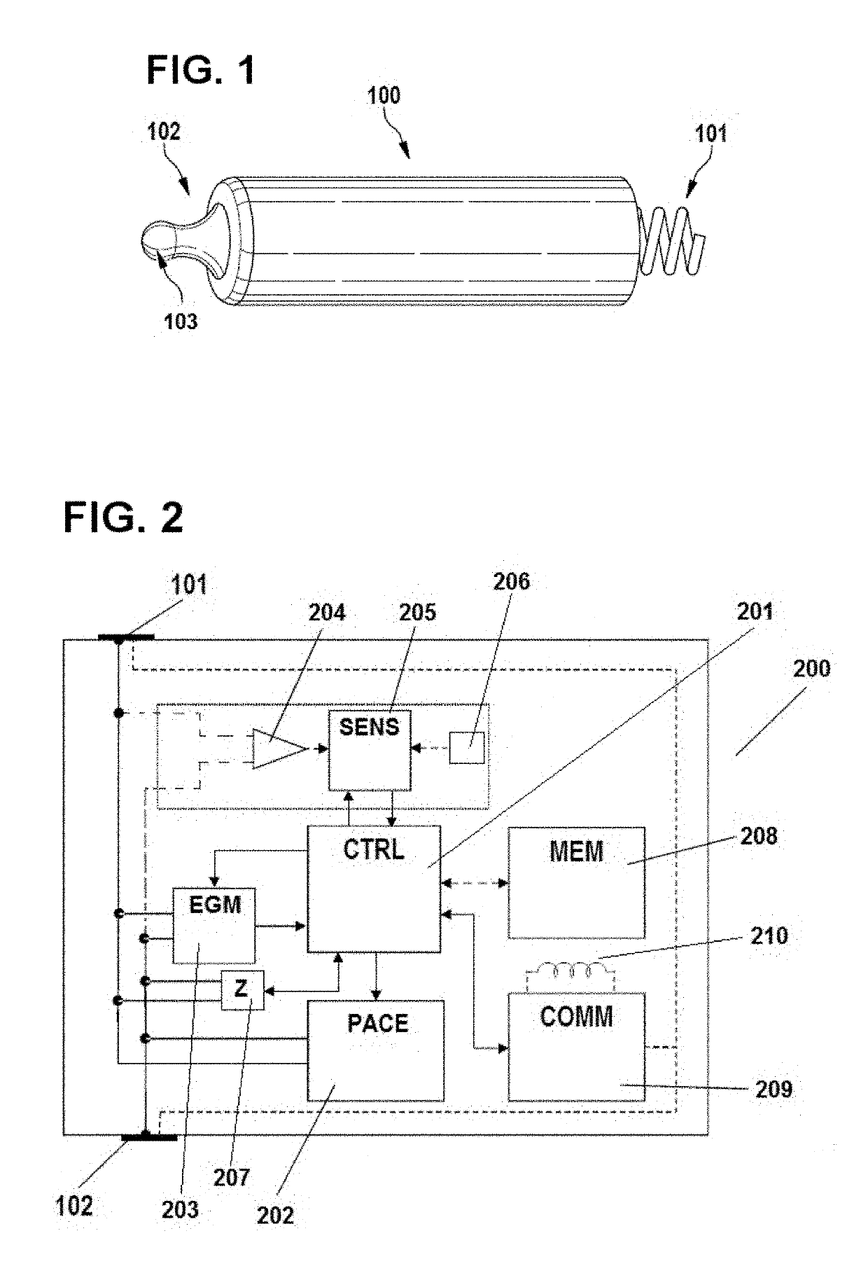
[0085]The invention is preferably implemented in a leadless pacemaker, with an exemplary leadless pacemaker 100 being illustrated in FIG. 1. The pacemaker 100 includes a pacing electrode 101 at one end, with the electrode 101 being configured to be anchored in the myocardium, and a return electrode 102 at its opposite end. The return electrode 102 may include a hitch 103, which facilitates implantation and explanation of the leadless pacemaker 100, as part of its active area. To decrease polarization, both electrodes 101 and 102 are preferably coated with fractal iridium (Ir). Electrically, the Helmholtz capacitance presented by electrode 101 (when implanted) is much smaller than the one presented by electrode 102 to reduce the pacing threshold and avoid anodic stimulation at the return electrode 102. The remainder of the case / can of the leadless pacemaker 100, apart from electrode 102, is electrically isolated (e.g. parylene coated), such that the electrodes 101 and 102 perform sim...


PUM


Abstract

A pacing system, which is particularly suitable for implantable leadless pacemakers, applies passively-balanced voltage-based pacing pulses, and periodically performs capture verification (evoked response detection) by following a pacing pulse with a current-based active balancing pulse, and then measuring any evoked response provoked by the pacing pulse. The active balancing pulse reduces residual charge on the electrodes used for pulsing, and thereby reduces polarization artifacts that could obscure measurement of the evoked response at the electrodes. The amplitude and pulse width of the active balancing current pulse are defined by measurements made in a few preceding pulses. The pacemaker preferably detects indicia of cardiac contractility, and performs capture verification only when contractility indicates that the patient is physically inactive and emotionally stable.

Description

CROSS-REFERENCE TO RELATED APPLICATION[0001]This application claims the priority, under 35 U.S.C. § 119(e), of provisional patent application No. 62 / 441,983 filed Jan. 4, 2017; the prior application is herewith incorporated by reference in its entirety.FIELD OF THE INVENTION[0002]This document concerns an invention relating generally to myocardial evoked response detection, and more specifically to evoked response detection systems suitable for use in implantable leadless pacemakers.BACKGROUND OF THE INVENTION[0003]Pacemakers are devices implanted in the body to stimulate the heart and regulate its contractions. Many pacemakers have housings which are implanted in the patient's chest or abdomen, and which have leads extending to the heart, wherein electrodes on the leads apply electrical stimulation. The pacemaker typically applies electrical stimulation having a fixed amplitude, one which is chosen with a safety margin that ensures successful “capture,” that is, the myocardium exhi...

Claims


Application Information

Patent Timeline
Patent Type & Authority Patents(United States)
IPC IPC(8): A61N1/37A61N1/375
CPCA61N1/3716A61N1/3756A61N1/3714A61N1/3702A61N1/37512A61N1/371
Inventor BARU, MARCELOVIJAYAGOPAL, RAMPRASADFRYER, ALAN
Owner BIOTRONIK SE & CO KG
Features
  • R&D
  • Intellectual Property
  • Life Sciences
  • Materials
  • Tech Scout
  • Unparalleled Data Quality
  • Higher Quality Content
  • 60% Fewer Hallucinations
Learn More