Powered surgical instrument with pressure sensitive motor speed control

a technology of motor speed control and surgical instruments, applied in the field of surgical instruments, can solve the problem that the clinical surgeon using the surgical device lacks control of the firing speed of the handle assembly

Active Publication Date: 2020-01-28
TYCO HEALTHCARE GRP LP
View PDF13 Cites 329 Cited by
  • Summary
  • Abstract
  • Description
  • Claims
  • Application Information

AI Technical Summary

Benefits of technology

[0018]Further, to the extent consistent, any of the aspects described herein may be used in conjunction with any or all of the other aspects described herein.

Problems solved by technology

However, a clinician using the surgical device lacks control of the firing speed of the handle assembly.

Method used


Image

  • Powered surgical instrument with pressure sensitive motor speed control
  • Powered surgical instrument with pressure sensitive motor speed control
  • Powered surgical instrument with pressure sensitive motor speed control

Examples


Embodiment Construction

[0027]Embodiments of the present disclosure are now described in detail with reference to the drawings in which like reference numerals designate identical or corresponding elements in each of the several views. As used herein, the term “clinician” refers to a doctor, a nurse, or any other care provider and may include support personnel. Throughout this description, the term “proximal” refers to the portion of the device or component thereof that is closest to the clinician and the term “distal” refers to the portion of the device or component thereof that is farthest from the clinician.

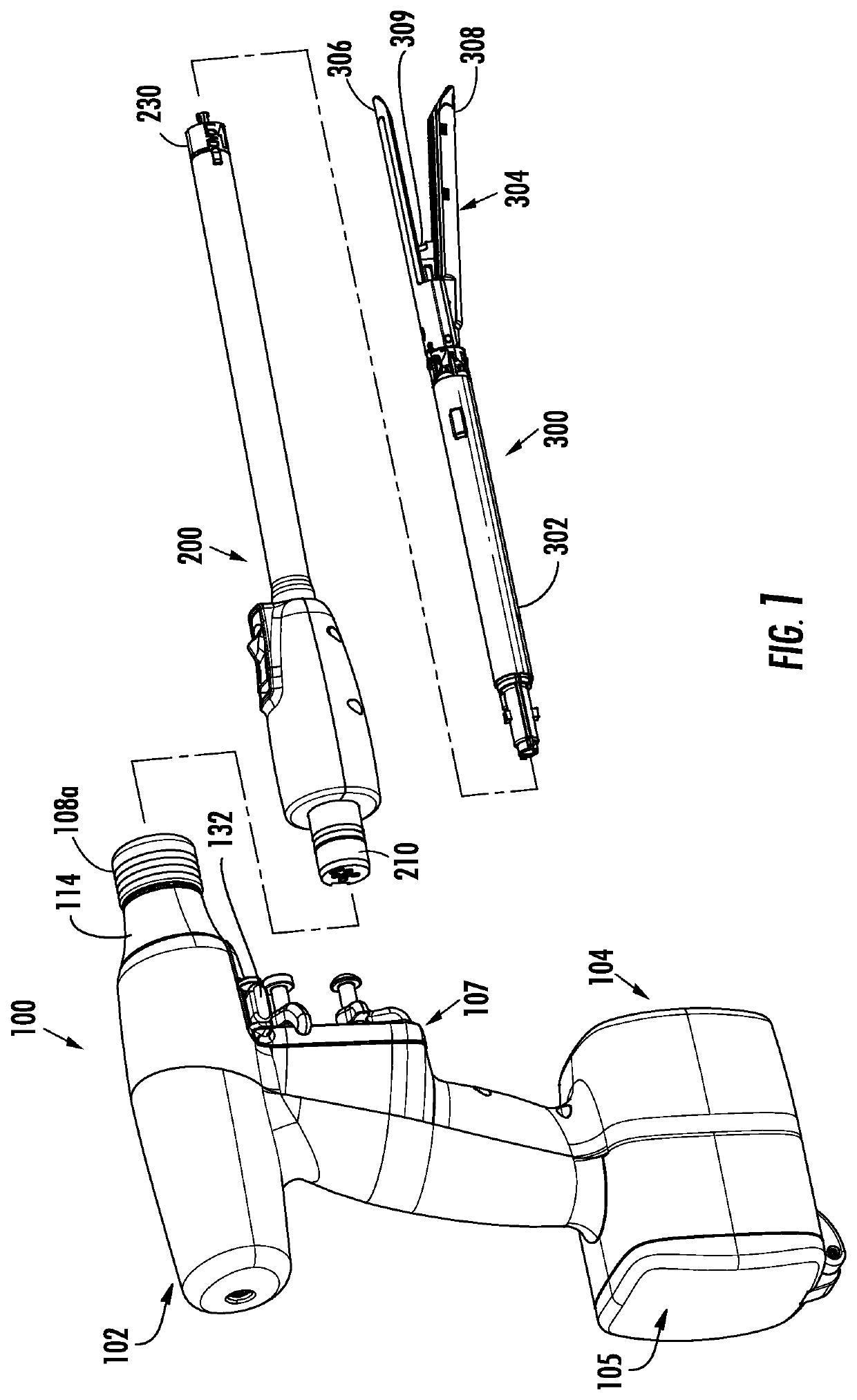
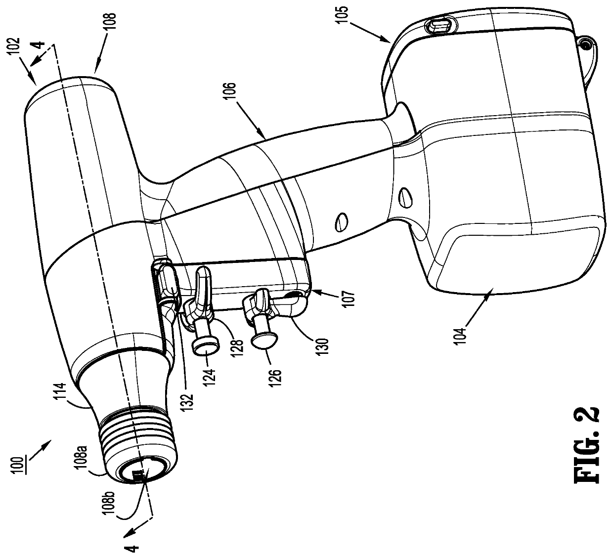
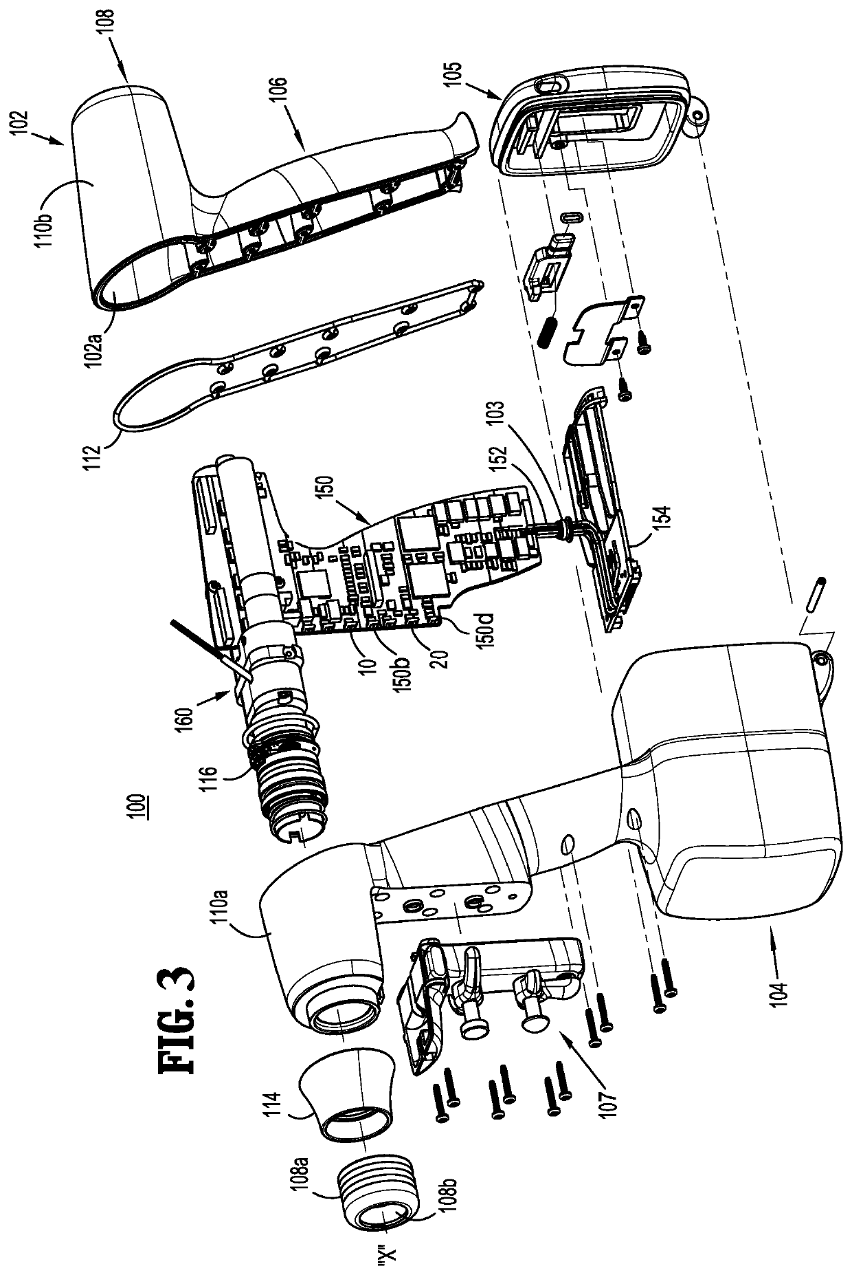
[0028]A surgical device, in accordance with an embodiment of the present disclosure, is generally designated as 100, and is in the form of a powered hand held electromechanical instrument configured for selective attachment thereto of a plurality of different end effectors that are each configured for actuation and manipulation by the powered hand held electromechanical surgical instrument.

[0029]As i...


PUM


Abstract

A surgical instrument includes a drive shaft, a motor for rotating the drive shaft, and a motor speed control. The motor speed control includes a first switch and a second switch which are in communication with the motor. The first switch is disposed over and in registration with the second switch. The first switch has an activated state such that the first switch sends a first signal to the motor. The motor rotates the drive shaft in response to the first signal. The second switch sends a second signal to the motor that varies the speed that the motor rotates the drive shaft in response to a force applied to the second switch by the first switch.

Description

CROSS-REFERENCE TO RELATED APPLICATIONS[0001]This application claims the benefit of and priority to U.S. Provisional Patent Application No. 62 / 031,340, filed Jul. 31, 2014, the entire disclosure of which is incorporated by reference herein.BACKGROUND[0002]1. Technical Field[0003]The present disclosure relates to surgical instruments and, more specifically, to speed control systems for powered surgical instruments.[0004]2. Discussion of Related Art[0005]A number of surgical device manufacturers have developed product lines with proprietary drive systems for operating or manipulating the surgical device. In many instances the surgical devices include a handle assembly, which is reusable, and a disposable end effector or the like that is selectively connected to the handle assembly prior to use and then disconnected from the handle assembly following use in order to be disposed of or in some instances sterilized for re-use.[0006]Many of the existing end effectors for use with many of t...

Claims


Application Information

Patent Timeline
Patent Type & Authority Patents(United States)
IPC IPC(8): A61B17/072H02P31/00H01H13/50A61B17/00
CPCH01H13/50A61B17/072H02P31/00A61B2017/00371A61B2017/07285A61B2017/00477A61B2017/07257A61B2017/00393A61B2017/00203A61B2017/07271A61B17/07207A61B2017/00464A61B2017/00017A61B2017/00137A61B2017/00389A61B2017/00398
Inventor CALDERONI, ANTHONYCHEN, XINGRUIDUSSAN, LUISPANTAZIS, JOHNCOLON, JAPHET
Owner TYCO HEALTHCARE GRP LP
Why Eureka
Try Eureka