
Lifting system and method for lifting and/or lowering loads

a technology of lifting system and load, applied in the direction of lifting frame, lifting device, lifting equipment safety device, etc., can solve the problems of vibration, more difficult a subsequent horizontal conveying operation, and accelerating operations that can be accelerated by considerable forces, so as to achieve less susceptible to faults, cost-effective effect, and straightforward

Active Publication Date: 2020-02-11
PENTANOVA CS GMBH
View PDF22 Cites 0 Cited by
  • Summary
  • Abstract
  • Description
  • Claims
  • Application Information

AI Technical Summary

Benefits of technology

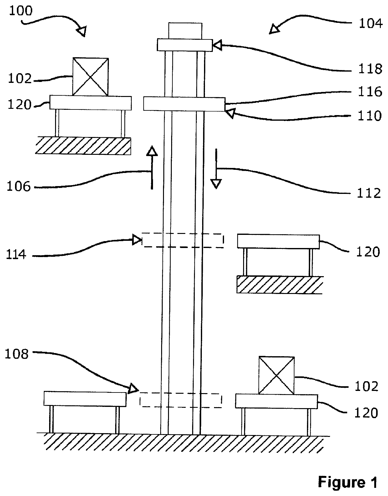
[0005]It is an object of the invention to specify a lifting system which is intended for lifting and / or lowering of loads and is straightforward, cost-effective and less susceptible to faults.

Problems solved by technology

The lifting carriage is used to move usually loads of large mass, for example, in a lifting cage or on a lifting platform, and therefore considerable forces can arise during accelerating operations, for example during start up, or during braking.
Although these forces are usually dissipated by the carrying structures of the lifting apparatus, the elasticity of the lifting means, for example cables or chains, involved may mean that, following completion of the lifting operation, vibrations occur and / or a lowering or lifting movement of the lifting cage or of the lifting platform takes place.
Such vertical movements taking place following completion of the lifting movement are undesirable and render more difficult a subsequent horizontal conveying operation, in which the loads located in the lifting cage or on the lifting platform discharge and are conveyed onward essentially horizontally.
The disadvantage with this solution is the fact that such a pinning device requires a drive, and possibly even a power supply on the movable lifting carriage.
In addition, the pinning device complicates the construction of the lifting system and therefore increases inherent susceptibility of the overall system to faults.

Method used


Image

  • Lifting system and method for lifting and/or lowering loads
  • Lifting system and method for lifting and/or lowering loads
  • Lifting system and method for lifting and/or lowering loads

Examples


first embodiment

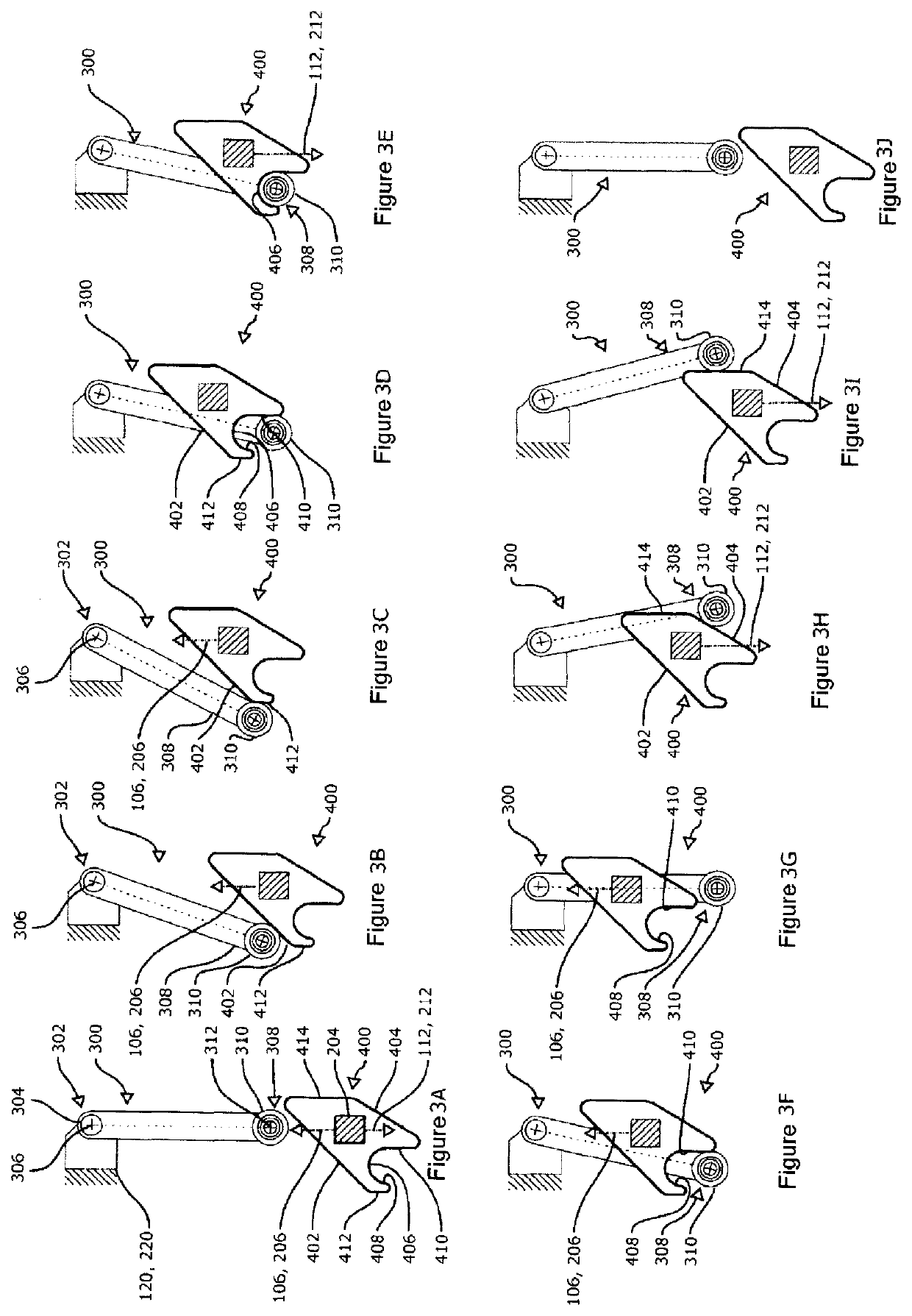
[0041]FIGS. 3A-3J show different positions of the retaining pendulum 300 and retaining holder 400 of a retaining-pendulum / retaining-holder combination. The retaining pendulum 300 is fitted preferably on a conveying apparatus, for example the conveying apparatus 120, 220, but in any case in a fixed state in relation to a conveying apparatus. In this embodiment, the retraining pendulum 300 is of inherently rigid design and has an upper end 302, at which a suspension or bearing point 304 is located. The retaining pendulum 300 is mounted at the bearing point 304 such that it can be pivoted about an axis 306, which in the present exemplary embodiment runs perpendicularly to the drawing plane. A lower end 308 of the retaining pendulum 300, said lower end being located opposite the upper end 302, has provided on it a roller 310, which is mounted such that it can be rotated about an axis 312, which in the present exemplary embodiment extends perpendicularly to the drawing plane. As an alter...

third embodiment

[0078]FIGS. 6A-6J show different positions of a retaining pendulum 300 and positions of a retaining holder 500 in a retaining-pendulum / retaining-holder combination.

[0079]Features of the retaining holder 500 which are the same as, or comparable to, those of the embodiment of the retaining holder 400 of FIGS. 3A-3J and 5A-5J are designated by reference signs to which 100 has been added.

[0080]The arrangement of the retaining pendulum 300 and retaining holder 500 corresponds, in principle, to the first and the second embodiments of FIGS. 3A-3J and 5A-5J. Accordingly, the retaining pendulum 300 is fastened in a rotatable manner on a conveying apparatus, for example the conveying apparatus 120, 220. In the case of this third embodiment, as already the case for the first embodiment, provision is made for the retaining pendulum 300 to be restored into its basic position exclusively under its own weight. In order to assist the restoring movement of the retaining pendulum 300, it is possible ...

fourth embodiment

[0089]FIGS. 7A-7J has a retaining holder 600 which, in a manner comparable to the retaining holder 500 of FIGS. 6A-6J, provides for guidance of the retaining pendulum 300 on just one side of the movement directions 106, 206, 112, 212 and, correspondingly, on just one side of the retaining holder 600. The retaining holder 600 itself has no first guide track 402, which could cause the retaining pendulum 300 to rotate clockwise in the first direction of rotation about the axis of rotation 306. A connecting contour 612 is provided, and this runs essentially parallel to the movement direction of the retaining holder 600. In the same way as for the previously described embodiments, a holding contour 606 is present, and this interacts with the free end 308 of the retaining pendulum 300 so as to provide for a supporting or latching action between the retaining pendulum 300 and retaining holder 600.

[0090]Alongside the actual retaining holder 600, two guiding-in structures 630, 632 are presen...


PUM


Abstract

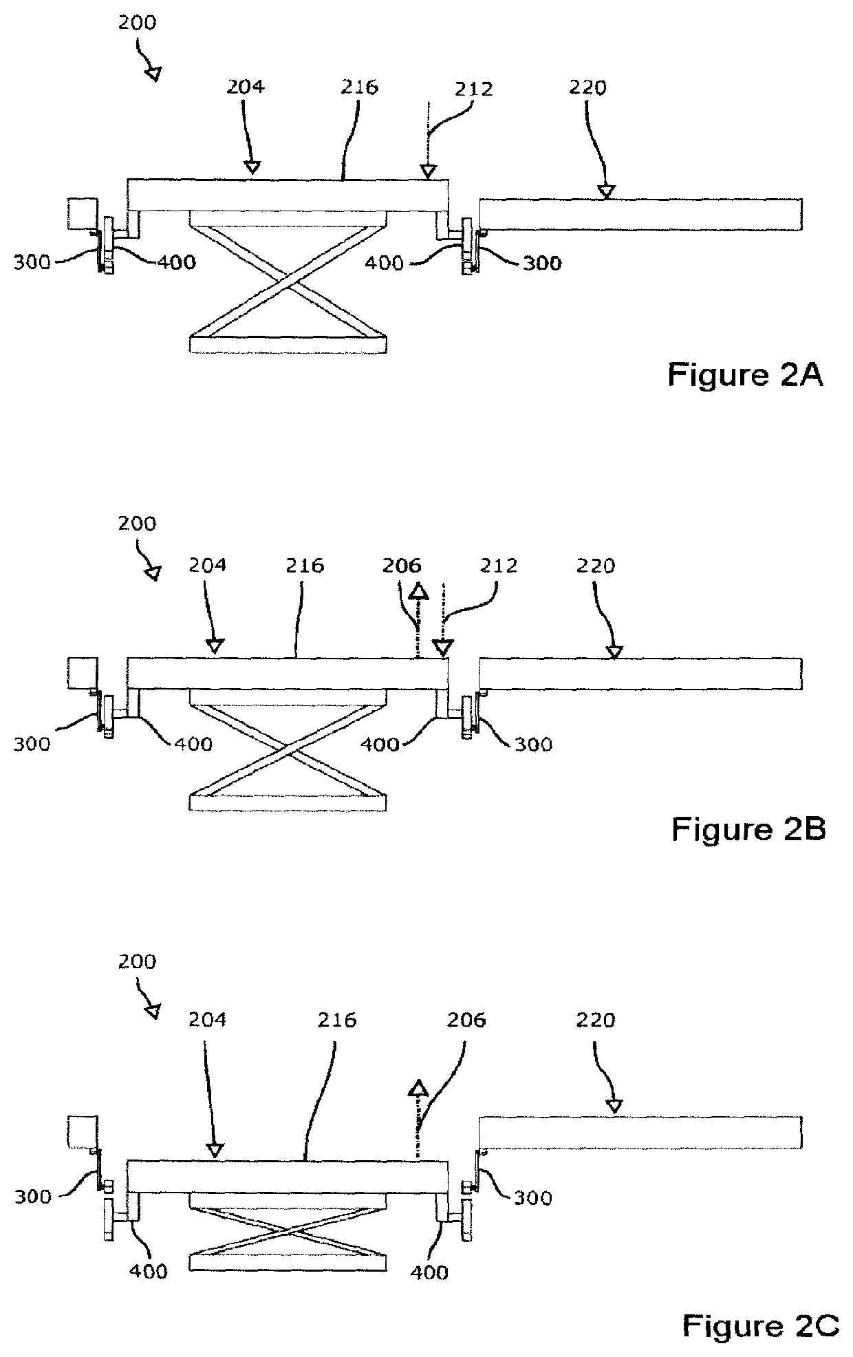
A lifting system for lifting and / or lowering loads having a lifting apparatus which is suitable for conveying loads along a lifting direction from a first transfer position into a second transfer position and along a lowering direction from the second transfer position to the first transfer position, and a conveyor apparatus which is suitable for taking on, at the first and / or the second transfer position, the loads conveyed by the lifting apparatus. The conveyor apparatus has at least one holding pendulum which is pivotable into a holding position, wherein the lifting apparatus has at least one holding receptacle for the holding pendulum, wherein the holding pendulum, in the holding position, can be placed in engagement with the holding receptacle, by a movement of the holding receptacle in the lowering direction, such that a movement of the lifting apparatus in the lowering direction is blocked, and / or the holding pendulum, in the holding position, can be placed in engagement with the holding receptacle, by a movement of the holding receptacle in the lifting direction, in such a way that a movement of the lifting apparatus in the lifting direction is blocked. The holding receptacle has a first guide track, wherein the first guide track is designed so as, during a movement of the holding receptacle along the lifting direction or the lowering direction, to move the holding pendulum into a first position in which the holding pendulum cannot be placed in engagement with the holding receptacle.

Description

RELATED APPLICATIONS[0001]This application is a national phase of International Patent Application No. PCT / EP2016 / 076605 filed Nov. 3, 2016, which claims priority to German Patent Application No. 10 2015 014 280.1 filed Nov. 6, 2015, the contents of both of which are incorporated herein by reference.BACKGROUND OF THE INVENTION1. Field of the Invention[0002]The invention relates to a lifting system for lifting and / or lowering loads, having a lifting apparatus, which is suitable for conveying loads along a lifting direction from a lower position into an upper position and along a lowering direction from the upper position to the lower position, and a conveying apparatus, which is suitable for receiving, at the lower and / or the upper position, the loads conveyed by the lifting apparatus.2. Description of the Prior Art[0003]Such lifting systems are known in the prior art. They are used in conveying technology for the vertical transportation of relatively large and often bulky loads, for...

Claims


Application Information

Patent Timeline
Patent Type & Authority Patents(United States)
IPC IPC(8): B65G17/18B66F9/02B66F17/00
CPCB66F9/02B66F17/00B66F7/00B66F9/00
Inventor RIEGRAF, MARTIN
Owner PENTANOVA CS GMBH
Learn More