
Method for blindness recognition in radar sensors for motor vehicles

a radar sensor and motor vehicle technology, applied in the direction of instruments, measurement devices, using reradiation, etc., can solve the problems of blindness of radar sensors, strong attenuation of radar signals, etc., and achieve the effect of reliable quantitative determination

Active Publication Date: 2020-02-11
ROBERT BOSCH GMBH
View PDF7 Cites 0 Cited by
  • Summary
  • Abstract
  • Description
  • Claims
  • Application Information

AI Technical Summary

Benefits of technology

The present invention provides a method for accurately determining the blindness of a radar sensor by measuring the degree of blindness through quantitative indicators. The indicators are largely independent of temperature, aging, and location, and can be increased in reliability and precision through statistical evaluation and combination of results from multiple objects. This method allows for more precise and differential evaluation of the radar sensor for various assistance or control functions, and ultimately ensures better reliability and precision of location data obtained from the radar sensor.

Problems solved by technology

In disadvantageous conditions, for example when a coating of slush forms on the radome of the radar sensor during heavy snowfall, the radar signals can be attenuated so strongly that in practical terms the radar sensor is blinded.

Method used


Image

  • Method for blindness recognition in radar sensors for motor vehicles
  • Method for blindness recognition in radar sensors for motor vehicles

Examples


Embodiment Construction

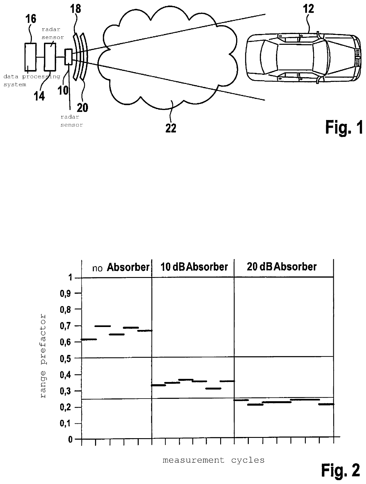
[0029]FIG. 1 shows a radar sensor 10 that is installed in the front part of a motor vehicle (not shown), and that is used to locate objects 12, such as vehicles traveling in front, and to measure their distances, relative speeds, and direction angles. A particular angular resolution capacity of radar sensor 10 also makes it possible to distinguish between broader and narrow objects, so that for example it can also be determined to what class of objects object 12 belongs, for example whether it is a passenger vehicle, a truck, or a two-wheeled vehicle, or possibly also a traffic sign at the edge of the roadway.

[0030]An electronic evaluation and control device 14 is used to control radar sensor 14 and to evaluate the received signals. The data ascertained in this way concerning the surrounding traffic situation are communicated, in digital form, to a data processing system 16 in which various driver assistance functions and / or autonomous vehicle guidance functions are implemented, for...


PUM


Abstract

A method for determining a degree of blindness of a radar sensor in a motor vehicle on the basis of a measurement of the receive power level of a radar echo, including the following steps that are carried out when at least one object is located by the radar sensor: determining an expected value for the radar scatter cross-section of the object on the basis of known properties of objects to be located; estimating the radar scatter cross-section of the located object on the basis of the measured receive power level; and calculating an indicator for the degree of blindness of the radar sensor as a monotonically increasing function of the difference between the estimated radar scatter cross-section and the expected value.

Description

CROSS REFERENCE[0001]The present application claims the benefit under 35 U.S.C. § 119 of German Patent Application No. DE 102016223068.9 filed on Nov. 23, 2016, which is expressly incorporated herein by reference in its entirety.FIELD[0002]The present invention relates to a method for determining a degree of blindness of a radar sensor in a motor vehicle on the basis of a measurement of the receive power level of a radar echo.BACKGROUND INFORMATION[0003]Radar sensors are used in motor vehicles to acquire the surrounding traffic, and supply location data such as distances, relative speeds, and directional angles of objects in the environment surrounding the vehicle. These location data are used as a basis for various driver assistance functions, such as automatic distance regulation, a collision warning system, or a collision avoidance system. The location data of such radar sensors are also required in systems for autonomous driving.[0004]In disadvantageous conditions, for example w...

Claims


Application Information

Patent Timeline
Patent Type & Authority Patents(United States)
IPC IPC(8): G01S7/40G01S7/35G01S13/93G01S7/41G01S13/931
CPCG01S13/931G01S7/4021G01S7/354G01S7/412G01S7/411G01S2007/4039G01S7/40G01S7/4039G01S7/4091
Inventor CHABAUD, MAIJAGROSS, VOLKER
Owner ROBERT BOSCH GMBH
Learn More