
Independently hydraulically clamped and sealed fitting

a hydraulic clamping and sealing technology, applied in the direction of fluid pressure sealing joints, pipe joints, couplings, etc., can solve the problems of complicated design, high cost of hydraulic type production, complicated installation, etc., and achieve the effect of simplifying the efforts required of the installer and high level of control over these operations

Active Publication Date: 2020-02-25
PIPE LINE DEVMENT
View PDF27 Cites 1 Cited by
  • Summary
  • Abstract
  • Description
  • Claims
  • Application Information

AI Technical Summary

Benefits of technology

The invention provides a pipe fitting that can be independently hydraulically gripped and sealed on a pipe with independent hydraulic systems to provide a high level of control over these operations. The hydraulic actuation of each of the gripping and sealing systems is through a single port connection, thereby greatly simplifying the efforts required of the installer. If desired, the hydraulic actuation can be performed through a line from a location remote from the fitting itself.

Problems solved by technology

The mechanical type can require numerous bolt tightening steps making installation complicated and time consuming, particularly when done underwater.
The hydraulic type can be expensive to produce, complicated in design, and difficult or not arranged to lock in place in a reliable and precise manner.

Method used


Image

  • Independently hydraulically clamped and sealed fitting
  • Independently hydraulically clamped and sealed fitting

Examples


Embodiment Construction

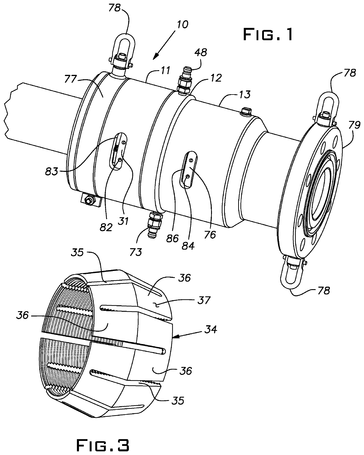
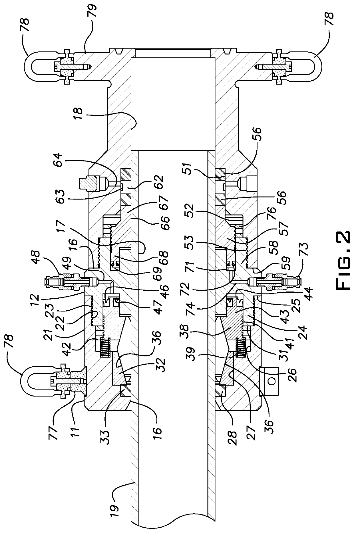
Referring now to the drawings, a pipe fitting 10 includes an axially extending circular housing formed by annular grip, middle, and seal sections 11-13, respectively. These parts and various other parts described hereinbelow are generally fabricated of steel, with the exception of seals, and are annular in form except for some accessories or small parts. The sections 11-13 are coaxial and each preferably has an inside diameter surface 16-18 adapted to receive the outside diameter of a steel pipe 19 with a loose slip or sliding fit.

A cylindrical skirt 21 on an inboard or inner end of the grip section 11 has internal threads 22 engaged with external threads 23 of a cylindrical extension 24 of the middle section 12. This enables the grip section 11 to be rigidly fixed to the middle section 12 with an end of the skirt 21 abutting a radial shoulder 25 of the middle section. The grip section 11 has several successive counterbores 26-28 inward of the internal skirt threads 22 for receiving...


PUM


Abstract

A pipe fitting comprising three annular coaxial sections including a grip section, middle section, and a seal section, the grip section and seal section being separately fixed to the middle section, an annular array of grips in the grip section, an annular semi-rigid seal in the seal section, a hydraulic grip actuator in the housing for radially constricting the grips into gripping engagement with an exterior of a pipe extending into the housing, and a hydraulic seal actuator hydraulically and mechanically independent of the grip actuator, for forcing the seal radially into engagement with an exterior of the pipe, a first mechanical lock for maintaining the grips in contact with the pipe and a second mechanical lock maintaining the seal in contact with the pipe.

Description

BACKGROUND OF THE INVENTIONThe invention relates to fittings useful in repairing and / or joining pipes.PRIOR ARTMechanically joined repair fittings, such as those for riser repair of submerged pipelines, are useful where it is impractical to weld. Prior pipe repair and maintenance fittings include mechanically clamped and sealed types as well as hydraulically clamped and sealed types. The mechanical type can require numerous bolt tightening steps making installation complicated and time consuming, particularly when done underwater. The hydraulic type can be expensive to produce, complicated in design, and difficult or not arranged to lock in place in a reliable and precise manner. There remains a need for a simplified, compact, independently hydraulically gripped and sealed pipe fitting.SUMMARY OF THE INVENTIONThe invention provides a pipe fitting that can be independently hydraulically gripped and sealed on a pipe with independent hydraulic systems to provide a high level of control...

Claims


Application Information

Patent Timeline
Patent Type & Authority Patents(United States)
IPC IPC(8): F16L37/62F16L17/10
CPCF16L37/62F16L17/10
Inventor LOUDEN, AARON Z.BEARD, GLENNMEENATHETHIL, SHON JOSEPH GEORGE
Owner PIPE LINE DEVMENT
Learn More