Demodulation of phase modulated signals using threshold detection

a phase modulation and threshold detection technology, applied in the field of demodulation of phase modulated signals using threshold detection, can solve the problem that the receiver capable of demodulating phase modulation can be highly complex

Active Publication Date: 2020-02-25
RAYTHEON CO
View PDF32 Cites 14 Cited by
  • Summary
  • Abstract
  • Description
  • Claims
  • Application Information

AI Technical Summary

Problems solved by technology

Receivers capable of demodulating phase modulation can be highly complex, requiring precision optics, local oscillators, gratings (such as Fiber Bragg Gratings), and / or delay line interferometers (DLI), etc.

Method used


Image

  • Demodulation of phase modulated signals using threshold detection
  • Demodulation of phase modulated signals using threshold detection
  • Demodulation of phase modulated signals using threshold detection

Examples


Embodiment Construction

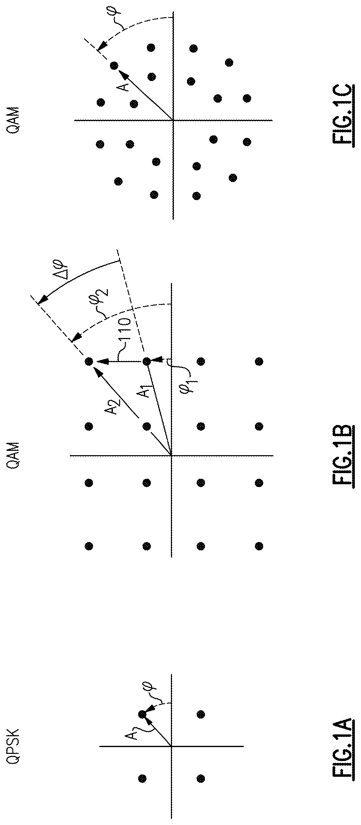
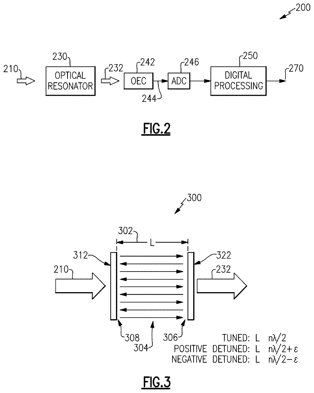
Aspects and examples described herein provide systems and methods for demodulation of phase encoded optical signals. In particular, certain examples of the system include a receiver having an optical resonator, such as a Fabry-Perot filter / resonator, micro-ring, or other resonator, for converting phase encoded optical signals into one or more intensity encoded optical signals. The intensity encoded optical signals may be easily converted to electrical signals (e.g., by an opto-electrical converter, such as a photodiode), and processed to determine phase variations in the received optical signal, at lower cost and complexity of the receiving system than conventional approaches.

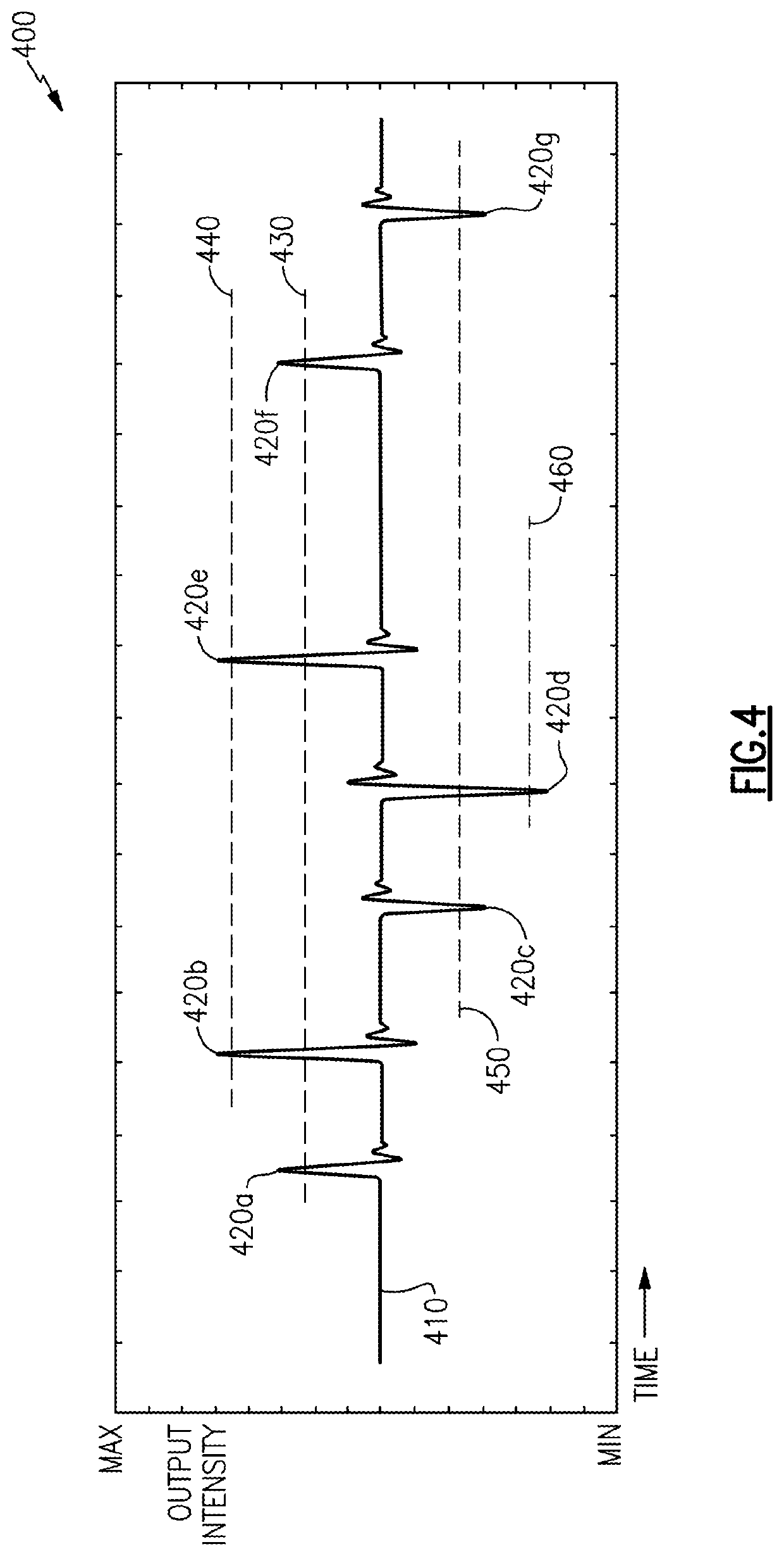
Aspects and examples described herein include a pulse detector, such as a threshold detector, to process the electrical signal to detect pulses (e.g., transients, disturbances) caused by phase transitions in the received optical signal. Detecting the timing and amplitude (optional) of such pulses may allow reco...


PUM

PropertyMeasurementUnit
phase transitionsaaaaaaaaaa
optical signalaaaaaaaaaa
electrical energyaaaaaaaaaa

Abstract

Optical receivers configured to demodulate phase modulated optical signals. In one example, an optical signal receiver includes an optical resonator configured to receive an arriving optical signal and to emit an output optical signal in response to receiving the arriving optical signal, the optical resonator being further configured to transform phase transitions corresponding to phase modulation of the arriving optical into intensity modulation of the output optical signal, an opto-electrical converter configured to convert the output optical signal into an electrical signal, a pulse detector configured to detect pulses in the electrical energy indicative of the phase transitions in the arriving optical signal, and a memory configured to record timing information associated with the pulses detected by the pulse detector.

Description

BACKGROUNDOptical signals may be made to carry information by modulating a light source, often a laser source, to change various properties of the light, such as its amplitude, phase, frequency, wavelength, etc. The light waves may be in the visible spectral band, the infrared spectral band, or another region of the electromagnetic spectrum. In some cases, an underlying signal, such as a radio frequency signal, may be modulated via amplitude, phase, or frequency modulation, or any combination thereof, and the light source may be modulated by the underlying signal. Optical receivers receive the light waves and measure properties or variations of the light wave, such as the amplitude, phase transitions, and the like, from which the underlying signal and the information may be recovered.Various light signals may include phase modulation, as well as amplitude or other modulation, that may encode information such as transmitted communication data, or may include other information such as...

Claims


Application Information

Patent Timeline
Patent Type & Authority Patents(United States)
IPC IPC(8): G02F2/00H04B10/67H04B10/69
CPCG02F2/00H04B10/697H04B10/676H04B10/677
Inventor GRACEFFO, GARY M.KOWALEVICZ, ANDREWDOLGIN, BENJAMIN P.
Owner RAYTHEON CO
Why Eureka
Try Eureka