
Radio transmission device, radio reception device, communication method, and communication system

a radio reception device and transmission device technology, applied in the field of radio reception devices, radio transmission devices, communication methods, communication systems, can solve the problems of reducing the possibility of terminal devices losing communication opportunities, affecting the service life of users, so as to improve the communication opportunities of new terminal devices and improve user throughput.

Active Publication Date: 2020-02-25
SHARP KK
View PDF18 Cites 0 Cited by
  • Summary
  • Abstract
  • Description
  • Claims
  • Application Information

AI Technical Summary

Benefits of technology

According to the present invention, it is possible to realize a wireless LAN system capable of improving communication opportunities of new terminal devices while securing communication opportunities of existing terminal devices, so it is possible to greatly improve user throughput.

Problems solved by technology

In the current wireless LAN system, interference due to an increase in the number of terminals per area is becoming a big problem, and it is necessary to consider such overcrowded environment in the IEEE 802.11ax standard.
However, in CSMA / CA which requires carrier sense prior to transmission, there is a problem that communication opportunities are greatly reduced due to interference between terminal devices under the overcrowded environment as described above.
Since the terminal device stops communication if interference not less than the CCA level is measured by carrier sense, increasing the CCA level reduces the possibility that the terminal device loses communication opportunities even in overcrowded environment.

Method used


Image

  • Radio transmission device, radio reception device, communication method, and communication system
  • Radio transmission device, radio reception device, communication method, and communication system
  • Radio transmission device, radio reception device, communication method, and communication system

Examples


first embodiment

1. First Embodiment

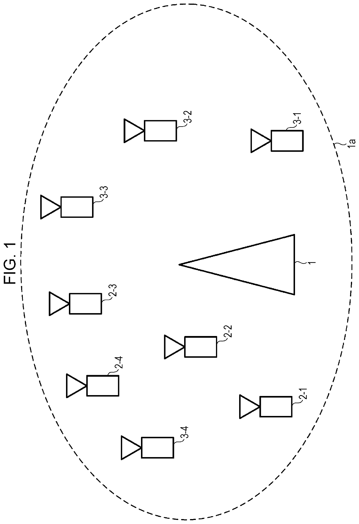
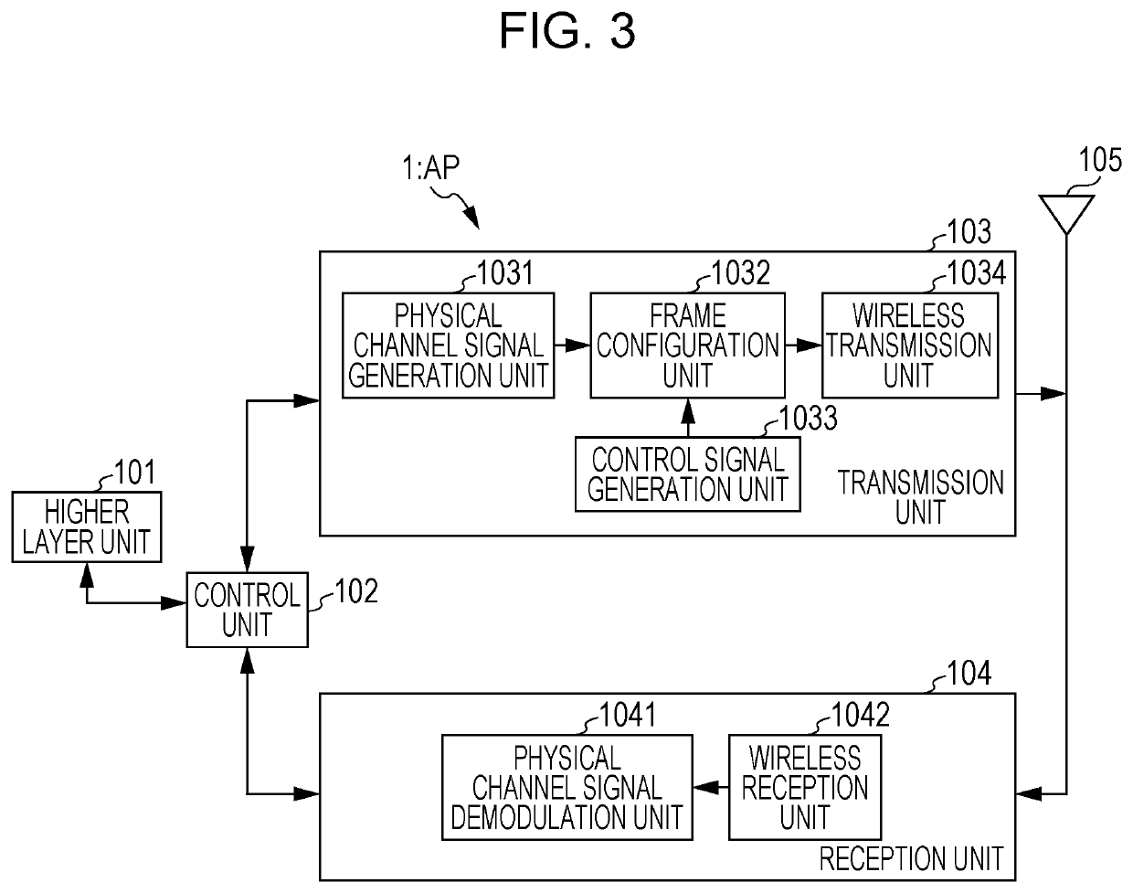
A communication system according to the present embodiment includes a radio transmission device (access point (AP)), and a plurality of radio reception devices (stations (STA)). Further, a network including the AP and the STAs is referred to as a basic service set (BSS).

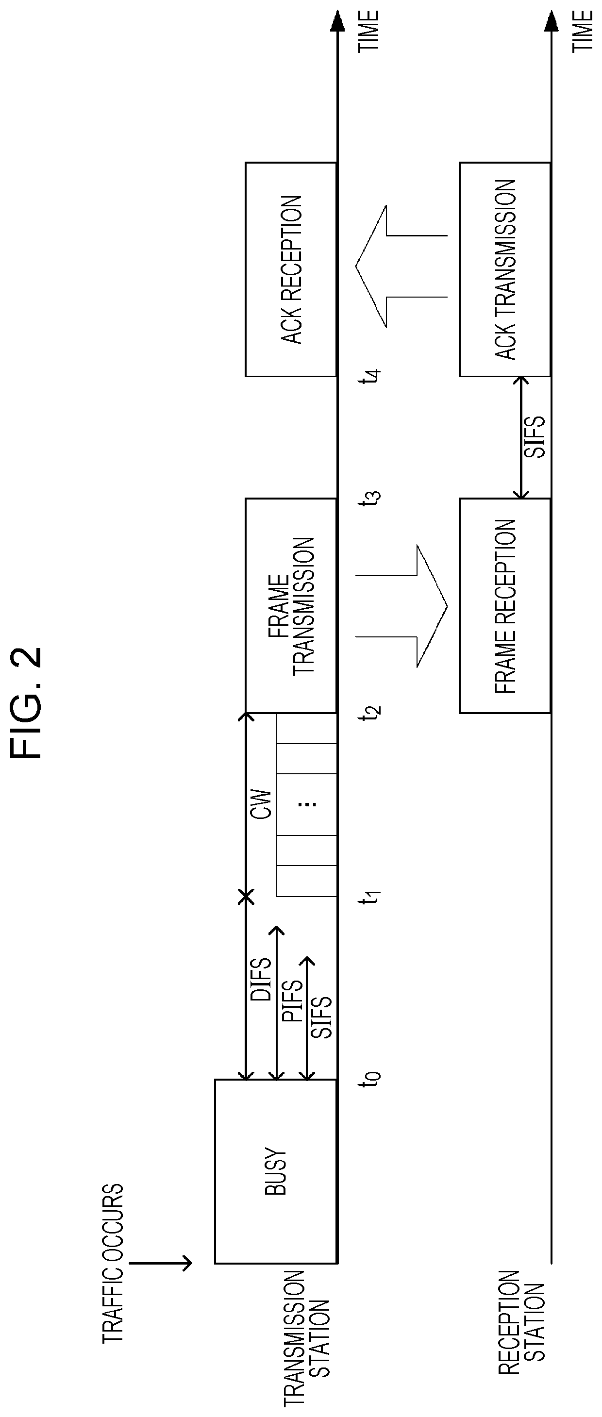
It is assumed that the AP and the STAs in the BSS respectively communicate with each other based on carrier sense multiple access with collision avoidance (CSMA / CA). The present embodiment is directed to an infrastructure mode in which the AP communicates with a plurality of STAs, but a method of the present embodiment can be implemented even in an ad-hoc mode in which the STAs directly communicate with each other.

In the IEEE 802.11 system, respective devices can transmit transmission frames of a plurality of frame types having a common frame format. The transmission frames are respectively defined by a physical (PHY) layer, a medium access control (MAC) layer, and a logical link control (LLC) laye...

second embodiment

2. Second Embodiment

In the communication system to which the embodiment is directed, the first CCA section and the second CCA section are switched by virtual carrier sense.

Since the outline of the communication system to which the embodiment is directed and the configurations of the AP 1 and the STA 2 are the same as those in Embodiment 1, the description thereof will be omitted. Similarly to the first embodiment, it is assumed that the AP 1 notifies the STA 2 of the first CCA level by a beacon frame or the like.

In the communication system according to the present embodiment, the AP 1 transmits a CTS-to-self frame (hereinafter referred to as a Legacy CTS-to-self frame or a second resource reservation frame) that can also be recognized by the STA 3, before the first CCA section. Since the CTS-to-self frame is a CTS frame in which the address of the transmission station is described in the destination address, the reception station that has received the CTS-to-self frame sets NAV acco...


PUM


Abstract

Communication opportunities of existing terminal devices are ensured, in a communication system in which terminal devices capable of using a new CCA level and the existing terminal devices using an existing CCA level coexist, on the premise of CSMA / CA. A communication method of a radio transmission device of the present invention includes a step of signaling information indicating a first CCA section and a second CCA section to the radio reception device. A communication method of a radio reception device of the present invention includes a step of performing the carrier sense based on a first CCA level and a second CCA level, and a step of performing the carrier sense based on the first CCA level, in the first CCA section, based on information indicating the first CCA section.

Description

TECHNICAL FIELDThe present invention relates to a radio transmission device, a radio reception device, a communication method, and a communication system.BACKGROUND ARTAs a development standard of 802.11n which is a widely practiced wireless local area network (LAN) standard, IEEE 802.11ac standard was defined by the institute of electrical and electronics engineers, Inc. (IEEE). Currently, standardization activities of IEEE 802.11 ax have been performed as a successor standard to IEEE 802.11 n / ac. In the current wireless LAN system, interference due to an increase in the number of terminals per area is becoming a big problem, and it is necessary to consider such overcrowded environment in the IEEE 802.11ax standard. On the other hand, in the IEEE 802.11ax standard, not only improvement in peak throughput but also improvement in user throughput is main requirements, unlike the past wireless LAN standard. It is indispensable to introduce a highly efficient simultaneous multiplexing t...

Claims


Application Information

Patent Timeline
Patent Type & Authority Patents(United States)
IPC IPC(8): H04W74/08H04W72/04H04W84/12
CPCH04W84/12H04W74/0808H04W72/0446H04W74/006H04W48/12H04W74/08
Inventor TOMEBA, HIROMICHIYOSHIMURA, TOMOKIONODERA, TAKASHI
Owner SHARP KK
Learn More