Other anomalies can also disrupt a straight line flight.
Typically, such smart bombs are not gyroscopically stabilized, since this stabilization tends to undermine steerability. en.wikipedia.org / wiki / Guided_bomb; http: / / science.howstuffworks.com / smart-bomb.htm
However, these systems are not generic.
One issue in guiding a rotating object is that the rotation gyroscopically stabilizes the projectile, and attempts to steer the projectile with modification of the axis of rotation, and off the gyroscopically stabilized flight path, result in reactive forces.
Each of these presents challenges, especially if the control system is to be self-contained within the projectile of reasonable size, weight and cost.
In some cases, where real time feedback is available and the actuator provides a small correction force with respect to the gyroscopic stabilization force, a prediction of reactive forces and effect is not required, though this imposes sometimes significant limitations on the control system.
Another issue is that in an inertial guidance system, the static G-forces in a rotating sensor platform may make quantitative analysis of small force perturbations more difficult.
Another issue is fragility.
In the case of a Frisbee or ball, the intended use subjects the projectile to harsh conditions, such as dirt, water, saltwater, mud, impacts, manual launch and grabbing, etc.
Therefore, even if the projectile meets a first aim of controlled flight path, unless it is also capable of surviving in harsh conditions, it will not meet a second aim of usability and context-appropriateness.
A rotating disk aircraft lacks obvious dynamic control opportunities, and the gyroscopic effects may be very significant during many types of control attempts.
Similar to a plane wing, this difference in pressure above the disc and below the disc results in lift.
This, in turn, causes a reaction force when the disk is spinning.
That is, for a normal Diskcraft disk, a vertical axis of rotation is less efficient than an inclined axis of rotation.
This suggests that the rotation has the effect of weakening the tip vortices which means that the disc loses lift.
Disc rotation also affects the tip vortices which leads to weakening of the shed vorticity, this in turn reduces the lift coefficient.
There is a concern that fixtures needed to support the ball in a wind tunnel may influence its drag.
Measurements of projectiles under game conditions have been attempted, but are difficult to interpret from the data scatter and are not controlled.
The drag crisis is apparent for both the golf ball and smooth sphere.
The drag crisis is a result of turbulence developing in the boundary layer of the ball.
Pitched balls (including knuckleballs) usually have some rotation and therefore do not achieve the low Cd.
However, for pitchers like Tim Wakefield, who can deliver a ball with no rotation, a pronounced drag crisis is more likely to occur, where the Cd could be as low as 0.26.
It is difficult to pitch baseballs with no rotation.
In this case, depending on the seam or stitch orientation, an asymmetric, and sometimes time-varying, flow field can be generated, thus resulting in an unpredictable flight path.
The boundary layer cannot typically negotiate the adverse pressure gradient over the back part of the sphere and it will tend to peel away or “separate” from the surface.
The pressure becomes constant once the boundary layer has separated and the pressure difference between the front and back of the sphere results in a drag force that slows down the sphere.
(Note that the turbulent process itself is dissipative, and therefore a mathematical model is complex or inaccurate).
The asymmetric separation and downward deflected wake are both apparent and result in an upward lift force on the spinning golf ball.
A short input (in control systems terminology an impulse) in pitch (generally via the elevator in a standard configuration fixed-wing aircraft) will generally lead to overshoots about the trimmed condition.
A short, sharp pull back on the control column may be used, and will generally lead to oscillations about the new trim condition.
If the oscillations are poorly damped the aircraft will take a long period of time to settle at the new condition, potentially leading to Pilot-induced oscillation.
If the short period mode is unstable it will generally be impossible for the pilot to safely control the aircraft for any period of time.
The damping term is reduced by the downwash effect, and it is difficult to design an aircraft with both rapid natural response and heavy damping.
In addition, if the wing has dihedral, side slip at a positive roll angle increases incidence on the starboard wing and reduces it on the port side, resulting in a net force component directly opposite to the sideslip direction.
If the wing has dihedral, this will result in a side force momentarily opposing the resultant sideslip tendency.
Anhedral wing and or stabilizer configurations can cause the sign of the side force to invert if the fin effect is swamped.
Roll rate generates fin lift causing a yawing moment and also differentially alters the lift on the wings, thus affecting the induced drag contribution of each wing, causing a (small) yawing moment contribution.
Yaw increases the speed of the outboard wing whilst reducing speed of the inboard one, causing a rolling moment to the inboard side.
This is in direct conflict with the Dutch roll stability requirement, and it is difficult to design a fixed wing aircraft for which both the Dutch roll and spiral mode are inherently stable.
Since the spiral mode has a long time constant, the pilot can intervene to effectively stabilize it, but an aircraft with an unstable Dutch roll would be difficult to fly.
Of course, most ordinary wings would be unstable if simply thrown through the air, but the essential mechanics of its lift are mostly ordinary.
Therefore, if one were to simply throw a flying disc, the lift would also cause a moment on the disc and cause it to flip over backwards.
Without the thick rim, throwing a flying disc would be significantly more difficult.
A stall occurs when the flow separates from an object, causing a catastrophic decrease in lift and increase in drag.
The disc will quickly destabilize and fall to the ground.
Although it is possible to spin an object about its long axis, this motion is not necessarily stable in the long term.
Specifically, internal energy losses force the object to ultimately rotate about the axis of maximum moment of inertia.
However, internal energy dissipation (for example, flexing of imperfectly elastic elements or flow of viscous fluids) can absorb energy.
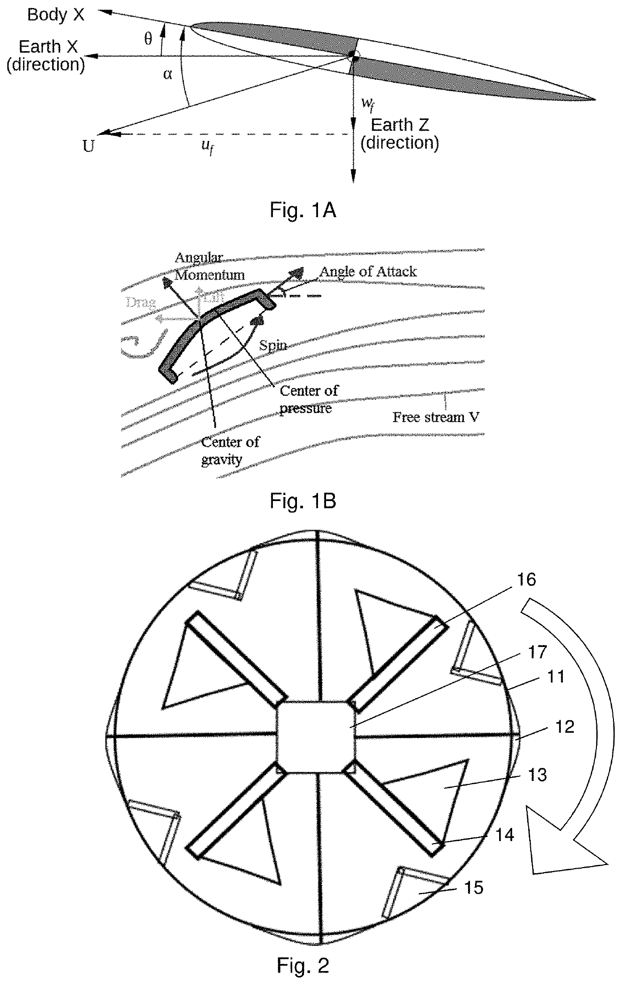
Because the COM and COP are not in the same place, there is a resultant pitch torque.
This bar can be faired with an aerofoil, but such a shape is harder to grip with the hands, and a cylindrical tube is rather cheaper.
This is sometimes true in a sense, but it is a rather misleading description—it fails utterly, for example, to explain why a flat or cambered plate can develop lift.
But it is not always true that the air flows faster across the upper surface.
Still other complications are introduced by spin, which may generate lift via the Robins-Magnus effect.
For the most part, the size range of balls used in sports is limited to the range that can be conveniently manipulated and thrown with a single hand.
While a “swing” that amounts to almost 1 m in the “pitch” length of 20m is possible at moderate speeds, such trajectories are only possible for a narrow range of throw speeds.
Although the ball is of a broadly similar size (9-9¼ inches, circumference) and mass (5-5¼ ounces avoirdupois) as a cricket ball, its motions are more complex since the stitching is not so simply arranged.
However, here the configuration of the seam does not permit a constant orientation by spinning.
There is inevitably some rotation, which has the effect of causing the seam to be presented at a range of angles to the flow and thus cause a varying, and therefore hard for the batter to anticipate, side-force direction.
Its size relative to the hand makes it much harder to impart spin to the ball.
Thus, although slower pitches give longer times for side-forces to act, and low flight speeds give higher advance ratios for a given spin, in general spin effects on softballs are rather modest.
The stretched prolate shape of balls used in American football and in rugby introduce complications.
Because of the tendency for aerodynamic moments to precess the ball, and the intrinsic instability of rotation around the axis of minimum moment of inertia, the ball tends to begin nutating, if not tumbling, towards the end of the throw.
Some of the ball's angular momentum is shed into the wake, which would ultimately cause the spin to decrease.
These are, however, only palliative measures that extend the duration of level flight-simple adjustment of shape and flight parameters cannot keep an object flying forever for the following reason: Spin stabilization only slows the destabilizing precession due to the pitch-up moment—the useful flight time is only a transient interval whose duration is proportional to the spin rate divided by the pitch moment.
Of course, if the pitch moment could be made zero, then the spin axis precession would take an infinitely long time.
The chains absorb the momentum of a correctly thrown disc and allow it to fall into the basket (without the chains, a disc would typically bounce off the pole, making scoring near-impossible).
First, the deep lip reduces the pitch moment to manageable values.
However, as the disc's speed falls off, its lift no longer balances weight, and it falls faster downwards, increasing the angle of attack.
The challenge in the Frisbee throw is that the overall flight is very sensitive to the initial parameters; small variations in angle of attack can lead to very different flights.
Because of the thickness of the disc required to suppress the pitch moment, the draggy Frisbee does not permit flights of extreme length.
However, this tuning (a cone angle of only about 1.5 degrees was necessary) was only strictly correct at one flight speed, and thus a perfectly trimmed condition was only found during a portion of a typical flight.
Although there will be some lift produced where the flow is backwards (depending on the twist or camber of the aerofoil), this will typically be rather low compared with the advancing blade.
In the (rather bad) case where the wings are perfectly flat or at least uncambered, the boomerang must have twist, such that both wings encounter a positive angle of attack and thus generate lift in the same direction.
As with the Chakram or Aerobie flying ring, this downwash reduces the effective angle of attack of the trailing side, and thus the lift force from it.

