Wind turbine rotor blade with vortex generators

a technology of turbine rotor blade and generator, which is applied in the direction of wind motors, wind motor control, motors, etc., can solve the problems of delay or prevent stall, increase of rotor blade load, and difficulty in retrofitting

Active Publication Date: 2020-03-24
SIEMENS GAMESA RENEWABLE ENERGY AS
View PDF20 Cites 0 Cited by
  • Summary
  • Abstract
  • Description
  • Claims
  • Application Information

AI Technical Summary

Benefits of technology

[0022]A hose has the advantage that it can be designed separately from the rest of the rotor blade and may also be exchanged easily after a certain time of operation.
[0027]A possibility to selectively embed the vortex generator is that in this case not only the ability to generate vortices is prevented or reduced but also the drag of the rotor blade. This is desirable because a reduced drag normally leads to an increase of the performance of the rotor blade and, hence, of the wind turbine. As mentioned above, it is preferred that the portion of the vortex generator which is embedded into the surface of the rotor blade increases with increasing stagnation pressure. This ultimately leads to a selective deactivation of the vortex generator with increasing stagnation pressure.
[0030]Again, in a preferred configuration, at high velocities of the airflow, the vortex generator is bent down towards the surface of the rotor blade and is consequently at least partially deactivated. This has the consequence that the ability to generate vortices is reduced.
[0031]If, on the other hand, the boundary layer thickness is large, thus, the stagnation pressure is small, the vortex generator moves away from the surface. Thus, a greater portion of the vortex generator is sticking out. In other words, the vortex generator projects away from the surface such that the ability of the vortex generator to generate vortices is increased.

Problems solved by technology

This re-energization of the boundary layer may delay or prevent stall.
This increase of the load of the rotor blade may be undesirable.
However, it is difficult to retrofit, for example, a rotor blade by a pressure chamber.
This ultimately leads to a selective deactivation of the vortex generator with increasing stagnation pressure.

Method used


Image

  • Wind turbine rotor blade with vortex generators
  • Wind turbine rotor blade with vortex generators
  • Wind turbine rotor blade with vortex generators

Examples


first embodiment

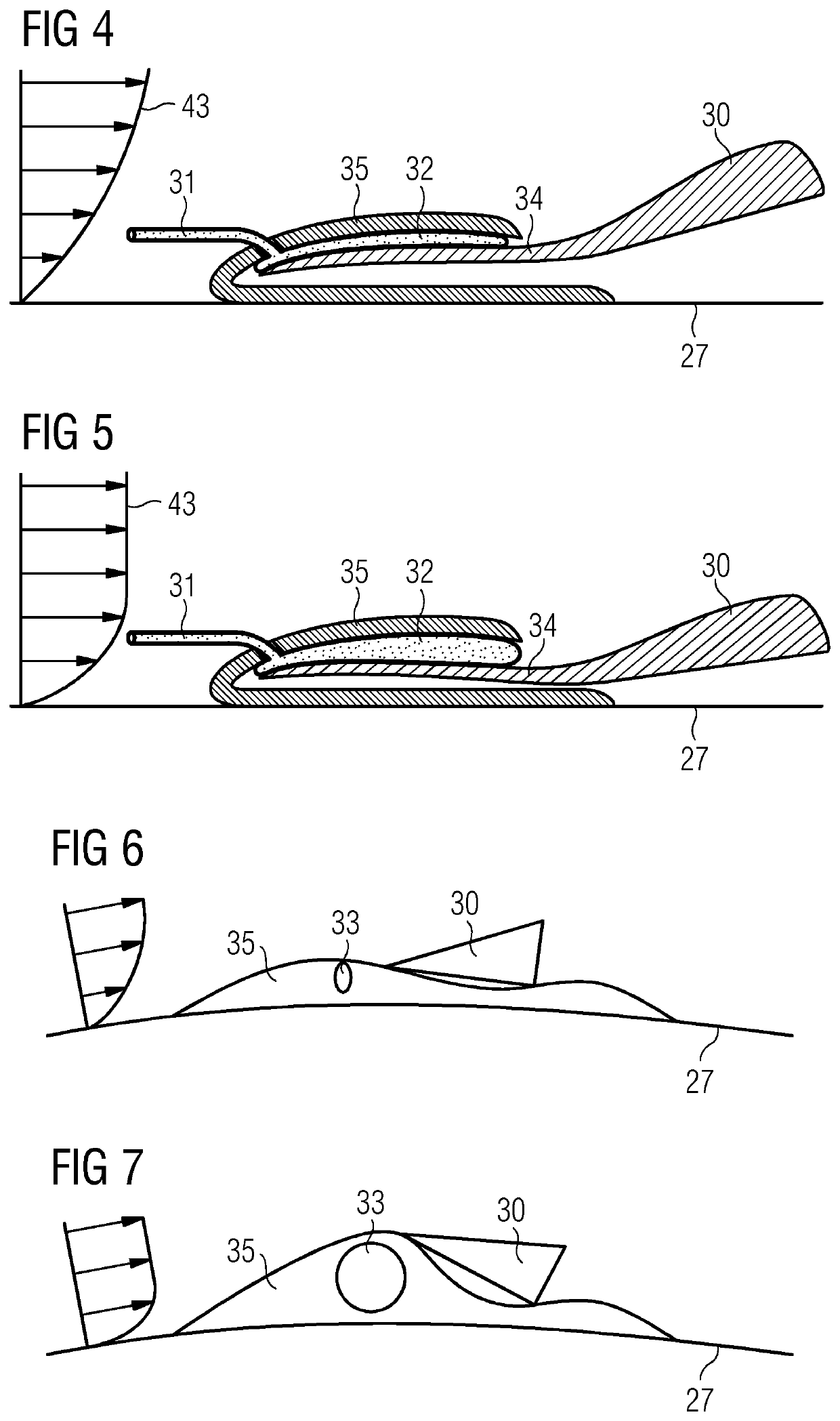
[0060]Note that in the invention, the housing 35 is designed as a relatively stiff and rigid element. This means that its shape is substantially independent on the state of the hose 32. Whether the hose 32 is inflated (as in FIG. 5) or not (as in FIG. 4)—the housing has the same cross-sectional profile. As a consequence, the airflow, which is passing over the housing 35 is not influenced by the fact whether the hose 32 is inflated or deflated.

second embodiment

[0061]FIGS. 6 and 7 shows the invention. Here, inflatable element is exemplarily designed as a pressure chamber 33. The pressure chamber may be in a deflated state (confer FIG. 6)—which is the case for a thick boundary layer, i.e. for a low stagnation pressure—or it may be in an inflated state (confer FIG. 7)—which is the case for a thin boundary layer, i.e. for a high stagnation pressure.

[0062]The pressure chamber 33 is accommodated and surrounded by a housing 35. In this embodiment, the housing is made of a flexible material. As a consequence, and contrary to the first embodiment as illustrated in FIGS. 3 to 5, the housing does change its shape depending of the state of the inflatable element.

[0063]Descriptively speaking, the housing 35 represents a “bump” for the airflow passing over it. Note that the airflow, which is passing over the housing 33, is influenced by the fact whether the pressure chamber 33 is inflated or deflated.

third embodiment

[0064]FIGS. 8 and 9 disclose a vortex generator. This time, the vortex generator 30 is partially embedded into the surface, e.g. into the suction side 27 of the rotor blade. In other words, the rotor blade is provided with a recess or groove at its suctions side 27. In this groove, a device or arrangement comprising a pressure chamber 33 can be seen. This pressure chamber is connected with a pressure tube 31. Depending on the stagnation pressure which is guided through the pressure tube 31, the pressure chamber 33 is either inflated (confer FIG. 9) or it is not or only slightly inflated (confer FIG. 8). As a consequence, the vortex generator 30 is either submerged and embedded into the surface of the rotor blade (confer FIG. 9) or it projects away and sticks out of the surface (confer FIG. 8).

[0065]This third embodiment has the advantage that additional drag from the attachment portion as shown in the first embodiment as illustrated in FIGS. 3-5, is avoided. Thus, additional drag fr...


PUM


Abstract

A rotor blade of a wind turbine including at least one vortex generator is provided. The vortex generator is attached to the surface of the rotor blade and is located at least partially within the boundary layer of the airflow flowing across the rotor blade. The vortex generator is exposed to a stagnation pressure, which is caused by the fraction of the airflow passing over the vortex generator and of which the magnitude depends on the velocity of the fraction of the airflow passing over the vortex generator. The vortex generator is arranged and prepared to change its configuration depending on the magnitude of the stagnation pressure acting on the vortex generator. Furthermore, an aspect relates to a wind turbine for generating electricity with at least one such rotor blade.

Description

CROSS-REFERENCE TO RELATED APPLICATIONS[0001]This application claims priority to European application No. EP 16178023 having a filing date of Jul. 5, 2016, the entire contents of which are hereby incorporated by reference.FIELD OF TECHNOLOGY[0002]The following relates to a rotor blade of a wind turbine comprising at least one vortex generator. Furthermore, embodiments of the invention relates to a wind turbine for generating electricity comprising at least one such rotor blade.BACKGROUND[0003]Vortex generators are well known devices for manipulating the airflow flowing across the surface of a rotor blade of a wind turbine. The function of a vortex generator is to generate vortices downstream of the area where the vortex generator is mounted to the surface of the rotor blade. The generated vortices may re-energize the boundary layer close to the surface of the rotor blade. This re-energization of the boundary layer may delay or prevent stall. The delay or elimination of stall at the ...

Claims


Application Information

Patent Timeline
Patent Type & Authority Patents(United States)
IPC IPC(8): F03D7/02F03D9/25F03D1/06
CPCF03D1/0675F03D7/0236F03D1/0633F03D7/022Y02E10/721F03D9/25Y02E10/723F05B2240/122F05B2240/31Y02E10/72F05B2240/3062
Inventor AKAY, BUSRAENEVOLDSEN, PEDER BAY
Owner SIEMENS GAMESA RENEWABLE ENERGY AS
Why Eureka
Try Eureka